
Chapter 17 of Naval Ordnance and Gunnery, Volume 2 — Fire Control covers exterior ballistics, the study of projectile motion after the projectile leaves the gun. Sections treat the forces affecting trajectories, the construction and use of range tables, practical computation of ballistic corrections, and target-practice post-firing analysis.
A. Forces Affecting Trajectories
17A1. Introduction
Exterior ballistics is by definition that part of the study of ballistics which deals with projectile motion after the projectile leaves the gun. A study of the entire subject of exterior ballistics includes theoretical aspects of this motion, the forces affecting it, and also the practical problems of laying a gun so that a projectile fired from it will hit the target. This text will deal primarily with the practical aspects of exterior ballistics. In a study of the subject, however, it is desirable to examine the characteristics of trajectories in general, as well as characteristics of trajectories of projectiles fired under specific firing conditions.
17A2. Definitions
The first step in the study of exterior ballistics is an understanding of the characteristics of a trajectory and of the applicable definitions and symbols.
Horizontal plane. The imaginary plane tangent to the earth's surface at a point instantaneously occupied by own ship. Any plane parallel to this one is also horizontal. Angles or distance measured in a horizontal plane are called horizontal angles or distances and are usually identified by the letter h.
Vertical plane. A plane perpendicular to the horizontal. Angles and distances measured in a vertical plane are called vertical angles or distances and are usually identified by the letter v.
Trajectory. The path described by a projectile in flight.
R — Range. The distance from the origin of the trajectory to the target along the LOS.
Rh — Horizontal Range. The projection of the range in a horizontal plane.
LOS — Line of sight. The straight line joining the sight and the target.
E — Position angle or target elevation. The vertical angle between the LOS and the horizontal plane.
Eg — Gun elevation (angle of elevation). The vertical angle between the horizontal plane and the axis of the bore.
Vs — Sight angle. The vertical component of the angle between the line of sight and the axis of the bore.
Angle of fall. The vertical angle between the horizontal and the tangent to the trajectory at the point of fall.
Maximum ordinate. The vertical distance from the horizontal plane to the highest point of the trajectory.
Tf — Time of flight. The total time which elapses during the flight of the projectile from the gun to the point of fall (or burst).
Df — Drift. The lateral deviation of the trajectory from the vertical plane through the axis of the bore caused by the rotation of the projectile.
Ds — Sight deflection. The lateral component of the angle between the LOS and the axis of the bore.
I. V. — Initial velocity of the projectile with respect to the gun muzzle at the instant the projectile leaves the gun (normally given in foot-seconds).
17A3. Trajectory analysis
Theoretically, the curved path taken by a projectile fired from a gun, when projected in a vertical plane, is caused by the force of gravity acting on the projectile after it leaves the gun. The path, projected on a horizontal plane, is also a curve, due to gyroscopic properties imparted to the projectile by rotation caused by the rifling in the gun. The effect of this gyroscopic force is called drift, and it is always to the right, because naval guns are rifled with right-hand twist. There are, however, other factors in addition to gravity and gyroscopic precessional force which modify the curvature of a trajectory.
If the projectile traveled in a vacuum, the only external force acting upon it would be that of gravity. Under such circumstances, the result would be vertical deceleration in the ascending branch until the summit was reached, followed by an exactly equal acceleration in the descending branch to the point of fall. This would result in:
1. A trajectory in the form of a parabola with a vertical axis.
2. A maximum ordinate located halfway between the gun and the point of fall.
3. An angle of fall equal to the angle of elevation.
4. A striking velocity equal to the initial velocity.
5. A maximum range obtained from an angle of elevation of 45 degrees.
When the projectile is fired in air, the theoretical trajectory in a vacuum is modified by air resistance, with the following results:
1. The trajectory is not a true parabola.
2. The angle of fall is greater than the angle of elevation.
3. The striking velocity is less than the initial velocity.
4. The maximum range of the projectile is obtained not precisely at, but still close to, an angle of elevation of 45 degrees.
For example, the maximum range of the 55.18-pound AA common projectile for the 5"/38 caliber gun is obtained with an angle of elevation of 44 degrees 35 minutes.
The following factors must be taken into account in ascertaining the difference in the trajectory characteristics of a projectile fired in air from the characteristics of one fired in a vacuum.
1. The density of the atmosphere. The air offers resistance to the projectile which materially alters the characteristics of the trajectory. Since atmospheric density differs from hour to hour with changes in temperature and barometric pressure, and also according to altitude, the resistance varies not only from time to time, but in the different altitude zones through which the projectile travels.
2. Characteristics of the projectile. The characteristics of a projectile which influence its retardation in passing through air of a given density are:
a. Weight.
b. Cross-sectional area, which is proportional to the square of the projectile's diameter.
c. Shape. A projectile which has a streamlined front end encounters less resistance than one which has a short, blunt nose. The shape of the base also affects resistance.
3. The initial velocity. With air density and projectile design constant, initial velocity affects the characteristics of the trajectory, because the amount of resistance offered by air varies with velocity.
17A4. Elements of a trajectory
Since the trajectory is curved, because of the factors mentioned, it is obvious that the bore of the gun cannot be pointed directly at the target (except at point-blank ranges), but that it must be directed at some other position in space, as shown in figure 17A1.

The projectile must describe a definite trajectory in order to hit the target. To obtain this trajectory, the gun must be laid accurately with respect to some reference plane or line. The horizontal plane provides a convenient reference plane from which the vertical angle may be measured. If the gun is mounted on a platform ashore it can be laid from the horizontal plane to the desired elevation by the use of a gunner's quadrant, an instrument which measures angles of elevation with respect to the true horizontal. At sea such a method is impracticable because of ship's motion. The most convenient reference is a line joining the positions of gun and target. Since it is normally the line along which the target is sighted from the gun, it is called the line of sight. Laying the gun with respect to this reference line is shown in figure 17A2. It is apparent from the figure that the gun elevation Eg remains constant as the ship rolls, as long as the LOS is held on the target.

The vertical angle through which the gun is elevated with respect to the horizontal is defined as the angle of elevation. If the trunnion axis is horizontal, the vertical angle between the axis of the bore and the line of sight is the same as the sight angle (Vs).
The lateral angular offset of the bore axis from the LOS due to the drift of the projectile is called drift (Df). The total lateral angle due to all factors causing deflection is called sight deflection (Ds).
17A5. Drift
The drift of an elongated, rotating projectile may be considered to result from three causes:
1. Gyroscopic action.
2. The Magnus effect.
3. The cushioning effect.
It is reasonably certain that the last two causes have only a minor effect as compared with the first.
The rifling of the gun barrel causes the projectile to rotate in flight with sufficient rapidity to behave as a gyroscope. This serves to stabilize the flight of the projectile, but it makes the projectile subject to gyroscopic precession. Because of the curvature of the trajectory, air pressure on the underside of the nose of the projectile causes a precession to the right. This shift of the projectile axis to the right increases the air pressure on the left-hand side of the nose, which causes the projectile to precess downward. This train of events continues, causing the axis of the projectile to oscillate about the tangent to the trajectory.
Since the greatest pressure is on the underside of the nose, the over-all precession is to the right.
The initial tendency of a projectile to maintain the original direction of its axis as it falls away from the axis of the bore causes the air stream to strike the projectile's lower side. With right-hand spin, the air adhering to the right-hand side of the projectile then opposes the air stream created by the projectile's flight, and the result is an increase of pressure on the right-hand side. At the same time, there is a rarefaction, and the projectile tends to move to the left, to the side of lesser pressure.
This effect is known as the Magnus effect, and is the same phenomenon which causes a golf ball to hook or slice. The Magnus effect can be important on the descending end of the trajectory at extreme elevations.
Since the air tends to pile up on the underside of projectile in motion, it forms a cushion. The projectile tends to roll on this cushion because of the friction imposed by it. This movement is to the right in a projectile with right-hand spin, opposing the Magnus effect but adding to the gyroscopic effect.
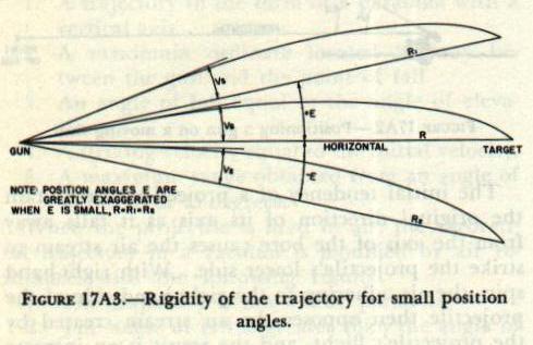
17A6. The principle of rigidity of the trajectory
When a gun is elevated with respect to its LOS, it is not necessarily elevated with respect to the horizontal, because the gun and target may not lie in the same horizontal plane. Assuming that the water's surface is the horizontal, the gun is placed somewhat above this surface, the exact distance depending on its location aboard ship. The LOS is normally directed at the waterline when the target is a ship. In this case, the LOS dips below the horizontal by the amount of the position angle E.
In the surface fire this angle E is small and may be neglected because of the principle of rigidity of the trajectory. This principle states that for small angles of position, a gun which obtains a certain inclined range along a line of position, when elevated the required angle above that line, will have the same range along the horizontal when elevated the same angle above the horizontal.
In surface fire it is unusual to encounter a position angle of more than about 35 minutes, and a value as great as this occurs only at extremely short range, in which case the gun elevation angle is also small. For example, with a 5"/38 caliber gun mounted 50 feet above the waterline and firing at the waterline of a target at a slant range along the LOS of 1,600 yards, the position angle is about -35 minutes and the gun elevation angle is +43.6 minutes. For these values of E and Eg, the ratio of the inclined range R to the horizontal range Rh is about 1.0001, showing that the difference in range is negligible. Therefore, even though the angles of elevation listed in the range tables are values of Eg (vertical angles measured with respect to the horizontal), these angles, when set on the gun sights as Vs (measured with respect to the line of position), result in the required ranges along the LOS, with insignificant error. This principle is applied only in surface fire, where the angles of position are normally small.
See figure 17A3.
The principle of trajectory rigidity does not hold in AA fire, because normally the position angle is considerably larger.
B. Range Tables
17B1. Preparation of range tables
For service use, the Bureau of Ordnance publishes for each gun and for each projectile type fired by the gun a range table, which presents, in convenient form for reference, the elements of the trajectories resulting from firing that specified projectile, at a specified initial velocity at various angles of elevation under standard conditions (which will be described later). A range table tabulates, for each 100-yard increment of range, such characteristics of the trajectory as angle of elevation, time of flight, angle of fall, and striking velocity.
It would obviously be impracticable to measure directly all the elements of the various trajectories, data for which appear in a range table. Neither is there a single simple equation whose solution will give the characteristics of a trajectory at any point, principally because of complications introduced by air resistance. The actual preparation of the range table involves experimental firings of a small number of the specified projectiles to obtain data which are used in conjunction with a complex set of equations or formulas to solve the trajectory.
The equations require (in addition to values of initial velocity and angle of departure) a value known as the Ballistic Coefficient, C, for their solution. This coefficient is a measure of comparison between the retardation of the specific projectile for which the range table is being prepared and the retardation of a projectile of a specific standard form in air of an arbitrarily chosen standard density. The expression for C is:
C = w / id²
where w = weight of projectile in pounds; d = diameter of the projectile in inches; i = coefficient of form (the ratio of the retardation of the given projectile to that of a projectile of standard characteristics).
The retardation of the projectile of standard characteristics which is being used as a basis for comparison is available in either the form of a drag coefficient or the form of a resistance curve. The data for such a drag coefficient or resistance curve are available from measurements obtained by actual experimental firings of the standard projectile. It should be noted that i will include not only retardation relations based on form, but any factors, other than weight and diameter, which affect retardation.
The value of the coefficient of form, i, is determined by experimental ranging at the Naval Proving Ground. A number of shots (from four to seven) are fired at each angle of elevation in a series such as the following: 5°, 15°, 20°, 30°, 45°, and again at 15 degrees. The velocity is measured at each angle. Throughout the firing, meteorological observations are made, at the surface and aloft, to determine wind, temperature, and atmospheric density. On the basis of these observations computations are made for ballistic density and ballistic wind for the predicted height of maximum ordinate. Since the projectile travels through various altitude zones, it is clear that values of wind, temperature, and density do not remain the same throughout the trajectory. Therefore, fictitious values of wind and air density are computed which represent a constant value for each over the entire trajectory. The fictitious values are called ballistic density, ballistic wind, and ballistic temperature; they are used for correcting the trajectories derived from observed data to those which would exist in the arbitrarily defined standard atmosphere on which retardation of the standard projectile is based.
Uncorrected observed ranges are recorded and averaged for each angle of elevation. These ranges are then corrected for errors due to: (1) the height of the gun above tide level, (2) the curvature of the earth, (3) jump, and (4) rotation of the earth. These corrections are in addition to the corrections for ballistic temperature, wind, and density mentioned above. The first two corrections mentioned in this paragraph permit the range table to conform to the requirement that the point of fall be in the horizontal plane tangent to the earth at the gun.
The corrected observed values are used to obtain a final coefficient of form, i, for each of the angles of elevation. From this the value of C for the designed weight and diameter of the projectile can be computed.
The observed lateral deviation is corrected for the effect of the component of wind acting at right angles to the line of fire and for rotation of the earth. The remaining deviation is the observed drift.
The formulas mentioned above can be used to solve for the elements at points on the trajectory, since the value of C is now available. Formerly, these formulas were worked out and assembled in ballistic tables for a number of combinations of the variables involved. The entering arguments of such a table are Eg, I.V. and C. From any combination of these three values it was possible to pick off the required values for the range table such as Range, Time of Flight, Angle of Fall, Maximum Ordinate, etc. The ballistic table can thus be considered as a master range table. It should be obvious that compilation of ballistic tables and construction of range tables from them entail much complicated and tedious work.
Current practice at the Naval Proving Ground is to compute all range table entries directly from the equations by means of large mechanical and electronic computing machines. These machines are capable of handling a large number of complex solutions rapidly and accurately, thus eliminating the need for ballistic tables. Obviously, in using computing machines in the preparation of range tables instead of using ballistic tables, a different method of arriving at the desired value is used rather than a change in basic principle of solution of the trajectory.
The computation of drift for standard conditions is a separate calculation involving the use of the observed drift in a special formula.
17B2. Standard conditions for range tables
In the computations upon which range tables are based, certain arbitrary conditions are assumed. These arbitrary conditions are generally spoken of as range-table standard conditions. In order to use the range table under conditions other than standard, it is necessary to provide in the range table, corrections for variations from these conditions.
The standard conditions assumed for range-table values are that:
1. The projectile leaves the gun with the designed velocity.
2. The projectile is of the designed weight.
3. The atmosphere is of an arbitrarily chosen standard density.
4. There is no wind.
5. The gun is motionless.
6. The target is motionless.
7. The earth is motionless.
8. The gun and target are in the same horizontal plane, the plane tangent to the earth's surface at the gun.
9. The gun is elevated in the vertical plane; that is, the axis of the gun trunnions is horizontal at the time of firing.
Since the range table is based upon these conditions, variations from any one of them may cause a significant error. In addition to the tabulation of trajectories under standard conditions, the range table provides necessary corrections for variations from the first six of these standard conditions. Corrections for variations from any of the last three require separate consideration or computation.
NOTE: Although motion of the target does not affect the trajectory itself, it enters into the problem of determining the trajectory that will reach the target.
Correction for rotation of the earth can be computed from auxiliary tables published with range tables for major-caliber guns, or by fire control instruments. The amount and direction of the error vary with the azimuth of the LOF, the latitude, and the range; but remain small in all cases. The correction is disregarded for guns of 5-inch caliber or smaller. The effect of firing at a target not in the horizontal plane of fire was discussed in article 17A6. The correction for tilt of the trunnion axis from the horizontal is practical only when using a mechanical solution and therefore is considered in chapter 19. Use of the columns of the range table to account for nonstandard conditions will be taken up in the next section of this chapter.
17B3. A typical range table
Appendix B contains extracts from the range table for the 8"/55 gun. The discussion which follows in this chapter, however, is based on the range table for the 5"/38 gun, which appears in appendix C. The discussion in section C of this chapter, “Practical Application of Range Tables,” is also based on the 5"/38 gun; and the tabular summaries of computations employ figures for the 5"/38 gun. A similar group of tabular summaries employing figures for the 8"/55 gun appears as part 6 of appendix B. The student may refer to these summaries also during the following discussion, since the computations are for the most part identical with those for the 5"/38 gun.
The range table shown in appendix C is for a 5"/38 caliber gun using a 55.18-pound AA common projectile. The table is based on an initial velocity of 2,500 foot-seconds, which is the average velocity obtained throughout the service life of a gun, instead of the value of 2,600 foot-seconds, which is the designed new-gun standard initial velocity. The use of such a base makes the required amount of correction from standard conditions smaller, considering the life of the gun, and therefore promotes accuracy in the final results.
Columns 1 to 8, inclusive, of the range table give values of elements of the trajectory, under standard conditions, corresponding to a given range, in increments of 100 yards. Columns 10 through 18 (there is no column 9) are needed because actual firing is seldom, if ever, conducted under standard range-table conditions. To compute accurate values for Vs (sight angle) and Ds (sight deflection) under actual firing conditions, it is necessary to determine corrections to the trajectory for any variations from standard.
The errors tabulated in columns 10 through 18 of the range table are those caused by a variation of +10 foot-seconds in initial velocity, −1 pound of projectile weight, −10 percent atmospheric density, −10°F. in temperature, or 10-knot components of wind, target, or gun motion. The sign is merely for convenience, so the tabulated values will usually be positive and not require a sign. Whether the correction is positive or negative will be readily apparent under the particular set of conditions of the problem.
17B4. Column 10
Column 10 is headed “Change of range for variation of +10 feet per second initial velocity.” The sole use of the plus sign in the heading is to indicate the direction of the error in range resulting from a variation from standard initial velocity, an increase in initial velocity naturally causing an increase in range.
The two elements which affect initial velocity are gun erosion and variation in powder temperature. Of these, erosion causes a loss in initial velocity and a decrease in range. The Navy range tables are based on a standard powder temperature of 90° Fahrenheit. Since magazine ventilation is regulated to ensure that the temperature in magazines hardly ever exceeds this figure, it is obvious that an increase in initial velocity due to powder temperature seldom occurs. The variation in velocity due to temperature variation of one degree from 90° F. is stated in certain range tables and other Bureau of Ordnance publications, a reduction in powder temperature causing a loss in velocity. The loss of initial velocity per degree change of powder temperature will vary with the caliber and powder index. However, 2 foot-seconds per degree F. change of powder temperature is about average, and will be used in this text for simplicity.
The loss of velocity caused by erosion is dependent upon the amount of bore enlargement, as was discussed in chapter 5 of this text. The range table includes one graph which shows the amount of velocity loss for specified amounts of bore enlargement, which can be used following star gaging, and a second graph showing bore enlargement versus equivalent service rounds fired, for use in periods between star gaging.
It must be noted that the loss of initial velocity for bore enlargement is, in the case of the 5"/38 caliber gun, a loss from new gun I.V. of 2,600 foot-seconds, 2,500 foot-seconds being the average velocity during the life of the gun; therefore, in a relatively new gun, velocity change due to bore enlargement may have to be computed, in relation to the range table, as a gain.
Having obtained the velocity loss from powder temperature and erosion data, as described above, one may determine the resulting range error from column 10.
Example: Find the range error due to a loss of initial velocity of 126 foot-seconds from new-gun standard for the 5"/38 caliber gun, firing at a range 10,000 yards.
Solution: From column 10, at range 10,000 yards, the error in range for a loss of velocity equal to 10 foot-seconds is −48 yards. A loss of 126 foot-seconds from 2,600 foot-seconds represents a loss of 26 foot-seconds from the range-table initial velocity. The error due to a loss of 26 foot-seconds is 26/10 × (−) 48 = −125 yards, or 125 yards short.
Note: A shot falling short of the target is termed a short, while one falling beyond the target is an over. Shorts and overs are corrected by add and drop spots, respectively.
17B5. Column 11
Column 11 is headed “Change of range for variation of −1 pound in weight of projectile.” This change of range is due to two causes which are opposite in their effects. The first is the change in the initial velocity. A projectile heavier than standard will be expelled from the gun at lower than designed muzzle velocity, causing a decrease in range. However, increase in weight will cause an increase in value of the ballistic coefficient and, since retardation varies inversely as the value of the ballistic coefficient, this causes an increase in range.
Referring to the range table in appendix C, part 2, it is seen that at short ranges, the effect on initial velocity is the predominant factor, while at long ranges, the effect on ballistic coefficient has the greater significance. At a range of 6,700 yards (in this table) the effects exactly cancel each other and the net error is zero.
In practice column 11 is not normally used aboard ship. It would be used if projectiles of other than standard weight were to be fired. Projectiles are required to be of designed weight within small tolerances, and the effects of these small variations are neglected, since it would obviously be impracticable to weight each projectile or to make a correction for each gun before firing each salvo. It is apparent, however, that this variation in projectile weight is one reason why all shots of a salvo, fired at the same time and under the same conditions, do not fall at the same point.
17B6. Column 12
Column 12 is headed “Change of range for variation in density of air of −10 percent.” For use under conditions where no aloft observations of air density are possible, a table has been prepared based on the results of many past observations aloft. The entering arguments are the height of the maximum ordinate in feet and the surface density; the result is the ballistic density. Standard surface density has been arbitrarily selected as the density of the atmosphere which results from a temperature of 59° F., a barometric pressure of 29.53 inches of mercury, and a humidity of 78 percent saturation. This standard surface density is assigned a numerical value of 1.000. To determine the variation in the trajectory caused by variation from standard surface density, the temperature and barometric pressure are measured at the surface and the resulting density is expressed as a percentage of the standard.
The minus sign in the heading of column 12 indicates that a reduction in air density causes an increase in range. Conversely, an increase in air density causes a decrease in range. In order to use the table for a given ballistic density, it is necessary to compare the percentage variations from standard with the 10-percent variation from standard on which the column is based.
Example: Given ballistic density of 1.059, find from column 12 the range error resulting from the non-standard atmosphere, for the 5"/38 caliber, 2,500-foot-second gun, firing at a range of 10,000 yards.
Solution: The percentage variation from standard is 1.059 − 1.000 = (+) 0.059 = (+) 5.9 percent. The value in column 12 is based on a (−) 10-percent variation from standard. The value taken from the column must, therefore, have a minus sign and the error is 5.9/10 × (−) 501 = −296 yards, or 296 yards short.
Note that the correction to compensate for this error in range is ADD 296 YARDS.
17B7. Use of the nomogram
An alternate means of determining the change of range for variation of air density is by nomogram. The nomogram provided with the 5"/38 caliber range table (appendix C, Part 1) is an example of the type in use in the fleet today. When aloft aerological observations are not available, it gives a rapid solution of the error in range due to variation in atmospheric density.
Instructions for its use are provided with the nomogram.
Example: Find the error in range for the 5"/38 caliber 2,500-foot-second gun, firing at range 10,000 yards, due to surface air temperature at 40° F. and surface barometric pressure of 30.10 inches of mercury.
Solution: Alignment of 40° and 30.10″ provides a point on the support line of the nomogram, which is the equivalent of determining the surface density. Alignment of that point with 10,000 on scale R gives an error in range of −280 yards. The necessary correction is, therefore, ADD 280 YARDS.
The use of the nomogram is more accurate than results obtained from using column 12 with surface observations, as it takes into account the ratio between mean measured and standard density for the actual maximum ordinate obtained.
NOTE: Some recent range tables, including the one reproduced in appendix C, have an additional column, 12a, which gives the change of range for a variation of temperature of the air of −10° F. from the standard air temperature. The effect given in column 12a is that caused by change in the elasticity of the air and is independent of and additional to the effect of any change in density. Column 12a is used with surface air temperature; the standard being taken as 59° F.
17B8. Columns 15 and 18
Column 15 is headed “Change of range for motion of target in plane of fire of 10 knots,” and column 18 is headed “Deviation for lateral motion of target perpendicular to line of fire, speed of 10 knots.” Actually, column 15 gives the distance that the target will move in the line of fire, if its speed in the line of fire is 10 knots, during the time of flight of the projectile. Column 18 gives the same information for motion across the line of fire. The values in the columns are derived by multiplying the speed of 10 knots, expressed as 16.89/3 yards per second, by the time of flight of the projectile for the given range, as found in column 4 of the range table.
Example: Find the errors in range and deflection caused by motion of a target, the components of whose speed are 16 knots in the line of fire and 13 knots across the line of fire, the firing ship being on the starboard bow of the target, range 10,000 yards.
Solution: Since the values in both columns 15 and 18 are found by multiplying speed components of 10 knots by time of flight, these values are identical, and are in this case 124 yards.
Then, in range, 16/10 × 124 = 198 yards that the target will move toward the firing ship during the time of flight. The correction to compensate for this motion must be DROP 198 YARDS.
Across the line of fire the target will move 13/10 × 124 = 161 yards to the right, and the correction to compensate for this motion must be to the right also.
It should be noted that target motion toward the firing ship will cause an error which is over in direction; also that target motion to the right will cause the projectile to fall to the left of the target position at the end of the time of flight. The correction, in each case, is in the direction of motion of the target.
17B9. Columns 13 and 16
Column 13 is headed “Change of range for wind component in plane of fire of 10 knots,” and column 16 is headed “Deviation for lateral wind component of 10 knots.”
A wind, or wind component, in the plane of fire, or line of fire, is spoken of as a range wind. A lateral wind (wind, or wind component, blowing across the line of fire) is spoken of as a cross wind.
The effect of a positive range wind (blowing in the direction in which the projectile is traveling) is to increase the range. The opposite is true for a negative range wind. A cross wind will carry the projectile in the direction toward which the wind is blowing. The method of deriving the values in these columns is quite involved, and will not be treated in this text.
The use of the columns is similar to that described in article 17B8, and will not be repeated. The direction of the errors having been found, care must be taken to apply the corrections in the proper direction. The error is in the direction toward which the wind is blowing; hence the correction must be in the opposite direction.
17B10. Columns 14 and 17
Column 14 is headed “change of range for motion of gun in plane of fire of 10 knots,” and column 17 is headed “Deviation for lateral motion of gun perpendicular to line of fire, speed, 10 knots.” By “motion of gun” is meant the velocity imparted to the projectile due to motion of the firing ship, aside from the velocity imparted by the powder charge.
This velocity may be positive or negative. Thus, a ship steaming at 10 knots and firing dead ahead imparts an added velocity of 16.89 foot-seconds, in the horizontal plane. The same ship firing dead astern reduces the horizontal component of initial velocity by the same amount. Firing on the beam causes a velocity component across the line of fire in the direction of motion of the ship.
If the gun were fired — and the projectile were to travel — in a vacuum, the range error could easily be determined. In the case of firing dead ahead, the range would be increased by 16.89 × Tf/3 yards. But this is the value found in columns 15 and 18, since the target motion was computed by using this very formula and with these same values.
However, the gun is not fired in a vacuum but in the resisting medium of the atmosphere. If no wind is blowing, a person standing on deck on a moving vessel will feel an apparent wind, equal in force to the speed of the vessel. It may therefore be said that a projectile fired from a moving vessel, in still air, is opposed by an apparent wind equal in force but opposite in direction to the motion of the vessel. The effect of such an opposing wind may be found in column 13 for range wind and in column 16 for cross wind.
The above discussion leads to the statement that “the effect of a given component of gun motion is, numerically, the equivalent of the effect of an equal component of target motion less the effect of an equal component of wind.” This does not mean that target motion, as such, enters into the problem in any way. It does mean that the value of the change of range if the gun were fired in a vacuum, would be computed in the same manner in which the effect of target motion is computed. This value is found in columns 15 and 18, which are tabulated as target motion. However, since the gun is fired in air, this effect is opposed by a force which is the same as that of an equal component of wind blowing against the projectile. This relation should be thoroughly understood, as it will be employed repeatedly in this text.
This statement may also be expressed as:
Column 14 = column 15 — column 13, and
Column 17 = column 18 — column 16.
Examination of any range table for any range shows that this relation is true. (The occasional difference of 2 or 3 yards is due to the fact that columns 14 and 17 actually are computed from formulas, the results plotted, and the curves faired.)
17B11. Danger space and hitting space
For a given target and trajectory, the danger space is the greatest distance through which the target may be moved in the line of fire and still be intersected at some point by that trajectory. Column 7 of the range table is composed of values of the danger space for a target 20 feet high and of zero depth in the line of fire.
Referring to the 5"/38 range table, range 10,000 yards, it is seen that the danger space is 18 yards. The value of the danger space at this range for a target 30 feet high is 30/20 × 18 = 27 yards. Now if this 30-foot target has a beam of 105 feet (35 yards) it is apparent that its danger space is 27 + 35 = 62 yards.
Hitting space is defined as the variation in sight-bar range, at a fixed target distance, between the trajectory which intersects a given target at the waterline and the trajectory which intersects the top of the target. Column 19 of the range table, headed “Change in height of impact for variation of 100 yards in sight bar,” is the column used for determining hitting space. (Sight-bar range is the range shown on the sight scale of the gun at the instant of firing.)

To find the hitting space for a 20-foot target at range 10,000 yards, column 19 is entered, and the value obtained is 112 feet; i.e., a variation in sight-bar range of 100 yards will move the point of impact 112 feet in the vertical plane of the target. To raise the point of impact 20 feet (to the top of the target) the sight-bar range would have to be increased 20/112 × 100 = 18 yards.
This value for hitting space is the same as that earlier obtained for danger space. For most battle ranges, this relationship holds; for the shorter ranges, however, there may be a considerable difference. For example with a 20-foot target at 3,500 yards the range table gives a danger space (column 7) of 157 yards and a hitting space of 20/14 (column 19) × 100 = 143 yards.
C. Practical Application of Range Tables
17C1. Definitions
For shipboard firings, it is necessary to determine, or to estimate, the variations from range-table standard conditions as they exist at the time of firing, and to compute corrections for the errors caused by these variations. The individual corrections are summarized and the result is called a ballistic correction.
Before this process can be described, it is necessary that the following terms be understood:
Line of sight (LOS) is the straight line joining the sight and the point of aim.
The line of fire (LOF) is the line joining the gun and the point of impact (or burst) of the projectile. The headings of some range-table columns speak of the “plane of fire,” others of the “line of fire.” The plane of fire is the vertical plane through the line of fire.
In this section no distinction will be made between “line of fire” and “line of sight.” It will be noted that the difference between the LOF and the LOS, if the problem is solved correctly, is that the LOS is based on present target position at the time of firing, while the LOF is based on the predicted target position. The errors caused by constructing the angles for target, wind, and own-ship motion about the LOS instead of the LOF are negligible in the case of surface-target firing. Only in antiaircraft fire, where the target speed is very high and the sight deflection or lead angle may be very large is it necessary to differentiate between LOS and LOF.
Relative target bearing (Br) is the direction of the target from the firing ship, relative to the bow of the firing ship. It is measured in a horizontal plane, clockwise from the bow of the firing ship to the line of sight, from zero to 360 degrees.
True target bearing (B) is the direction of the target from the firing ship, relative to geographic north. It is measured clockwise in a horizontal plane from true north to the line of sight, from zero to 360 degrees.
Target angle (A) is the relative bearing of the firing ship from the target. It is measured in a horizontal plane clockwise from the target's bow to the firing ship, from zero to 360 degrees.
True wind is the wind as it exists with respect to the earth and independent of any motion of the ship.
Apparent wind is the wind which is apparent to an observing station which is itself in motion. It is the vectorial resultant of the motion of the true wind and the reversed motion of the observing station.
Ballistic wind is a value of wind speed and direction which is considered to be the resultant of the effect of all the true winds acting upon the projectile in flight. The resultant, computed as a vectorial sum, is used as though it were a uniform wind, constant throughout the trajectory. If no means is available for determining ballistic wind, corrections for wind are based on the existing surface wind.
Wind direction is the direction from which the wind is blowing. The term is applied to either true or apparent wind.
17C2. The line-of-sight diagram
In order to compute the errors caused by target motion, wind motion, and firing-ship (gun) motion, it is necessary to resolve these motions vectorially into components, in and across the line of sight. The diagram which is employed is called a vector diagram. A simple problem, with explanation of each step, will best illustrate how this solution is obtained.
Given: 5"/38 caliber gun. Range, 10,000 yards. Relative target bearing, 300 degrees. Target angle, 80 degrees. Wind direction, true wind, 255° relative. Firing ship's speed, 18 knots. Wind velocity, 10 knots. Target speed, 20 knots.
Required: Draw the vector diagram for this situation; compute the components of gun, wind, and target motions in and across the line of sight. Determine whether the resulting errors will be over or short in range and right or left in deflection.
Solution:
a. Draw a vertical line representing the direction of the line of sight. This is always drawn as a vertical line with own ship (gun) at the bottom of the line. Mark the points, T, W, and G from which to draw vectors for target, wind, and gun motions, respectively.
b. Since relative target bearing is 300°, the angle measured clockwise from firing ship's bow to the LOS is 300 degrees. The gun-motion vector is drawn making this angle with the LOS. The acute angle between the gun's vector and the LOS is seen to be 60 degrees. (The acute angle is used in the determination of the components.) By trigonometry, the component of gun motion in the LOS is 18 cos 60°, or 9.0 knots, and the component across the LOS is 18 sin 60°, or 15.6 knots, as shown in figure 17C1.

The component in the LOS, in this case, results in imparting to the projectile an added velocity which causes increase in the range over that which would be attained were the firing ship stationary. Had the gun component in the LOS been in the opposite direction, or away from the target, the result would have been a decrease in the range. The range is increased, and the error is over. The vector should be so labeled.
By the same reasoning, the gun motion component across the LOS imparts a lateral velocity and a deflection error in the direction of the component. In this case the error is right and the vector should be so labeled.
c. From W lay off the true-wind vector for a wind direction relative to the bow of the firing ship equal to 255 degrees. The bearing of the LOS is 300° from the bow of the firing ship. Hence the direction from which the wind is blowing, with respect to the LOS, is 255° − 300° = (−) 45°. This angle is laid off at W, counterclockwise from the LOS. Since the wind velocity is 10 knots, the component in the LOS is 10 cos 45° = 7.1 knots. The result of this wind component, acting on the projectile during the time of flight, is to cause a reduction in the range, or a short error. The component across the LOS, 10 sin 45° = 7.1 knots, blows the projectile to the right, causing a right error in deflection. The vector should be labeled short and right.
d. From T lay off the target vector so that the target angle equals 80 degrees. The component in the LOS is 20 cos 80° = 3.5 knots, and across the LOS is 20 sin 80° = 19.7 knots.
During the time of flight the target is decreasing the range at the rate of 3.5 knots, and a projectile fired with the given range setting will fall beyond the target's position at the end of the time of flight. Hence the range error caused by this motion of the target is over. Also since the target moves to the right the projectile will fall to the left of the position of the target at the end of the time of flight, or the error in deflection will be left. The vector is therefore labeled over and left.
e. Having determined the direction of the errors, in range and in deflection, caused by gun, wind, and target motions, it is now necessary to determine, from columns 13–18, inclusive, the amounts of these errors in yards.
17C3. The gun ballistic correction
In gunnery, a correction for an error in range or in deflection is known as a ballistic correction. The ballistic correction to compensate for the errors noted below is known as the gun ballistic correction. These elements are:
In Range: (1) Variation in powder temperature; (2) Velocity loss due to gun erosion; (3) Variation in air density; (4) Target motion in the LOS; (5) Wind motion in the LOS; (6) Gun's velocity in the LOS; (7) Earth's rotation (major caliber).
In Deflection: (1) Drift; (2) Target motion across the LOS; (3) Wind across the LOS; (4) Gun's velocity across the LOS; (5) Earth's rotation (major caliber).
The example given in article 17C2 will be continued to find the gun ballistic for that situation, with further variations due to powder temperature 80° F., velocity loss due to erosion 18 foot-seconds (below 2,500 foot-seconds), and atmospheric density corresponding to surface air temperature 52° F. and barometer 30.40 in.
The multiplier for column 12 (variation in air density) is found by first obtaining from the aerological party a value of ballistic density factor, in this case 1.043. Then: 1.043 − 1.000 = 0.043 = (−) 4.3%. Since column 12 is based on a 10 percent variation, the multiplier is (−) 4.3/10, or (−) 0.43. The minus sign indicates that the range error will be short.
The powder temperature is 10° less than standard, causing a velocity loss of 2 × 10 = 20 foot-seconds.
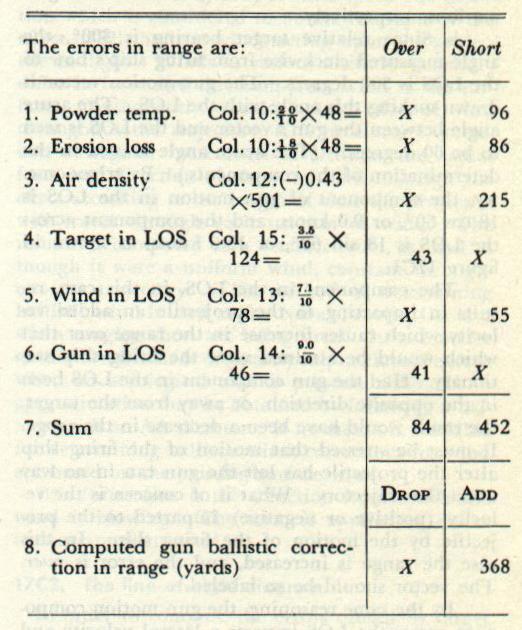
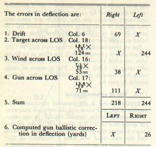
Note the arrangement of column headings. Item 7 shows the sums of the over and short errors. Item 8 shows the algebraic sum of these errors (452 − 84 = 368), tabulated in the same column as the larger of the two. The correction thus derived represents ADD 368 YARDS. The algebraic sum of the errors in deflection is 26 yards to the left; the computed gun ballistic correction is RIGHT 26 YARDS. As a last step, it is necessary to convert the ballistic correction in deflection from yards to mils by dividing by the range in thousands of yards (26 ÷ 10 = RIGHT 0–3).
17C4. Motion of own ship
In the headings of range-table columns 13 and 16, neither true wind nor apparent wind is specified. If the gun were fired in a vacuum, the additional horizontal velocity imparted to the projectile by the motion of own ship would be equal in effect to equivalent target motion.
However, the gun is fired in air, which for purposes of this discussion is assumed to be motionless. Now, the movement of own ship through this still air creates a wind apparent to a person on the ship. This apparent motion of the wind is equal in speed but opposite in direction to ship motion. Its effect is partially to nullify the extra velocity imparted by own ship, for it acts on the projectile just as though it were an actual wind. Thus, the effect of a component of own-ship motion (column 14 of range table) is numerically equivalent to the effect of an equal component of target motion (column 15 of range table) less the effect of an equal component of wind (column 13 of range table), as was pointed out in article 17B10.
If true wind is used, gun motion, from columns 14 and 17, will include the effect of the wind set up by own-ship motion. If apparent wind is used, the use of columns 14 and 17 for gun motion would result in correcting for this wind effect twice. Therefore, when apparent wind is used, gun motion is the numerical equivalent of target motion, and errors due to gun motion must be calculated using columns 15 for range and 18 for deflection. This is referred to as “treating gun motion as target motion.”
17C5. Use of apparent wind
Apparent wind is the vectorial resultant of the motion of the true wind and the reversed motion of the observing station (article 17C1). In the example given in article 17C2, the relative target bearing was 300°, own ship's speed 18 knots, and the true wind was from a direction of 255° relative, velocity 10 knots. The apparent wind is determined vectorially as illustrated in figure 17C2.


The values of the components of the apparent wind are obtained by taking the algebraic sum of the true wind components, Xw and Yw, and the reversed own-ship components, Xo and Yo. The combined components of gun and target motions in range are 9.0 + 3.5 = 12.5 knots, both components decreasing the range and causing an over error. In deflection the algebraic sum is 19.7 L − 15.6 R = 4.1 L. The gun ballistic correction recomputed using apparent wind is practically identical with that obtained in article 17C3, confirming the conclusions drawn in articles 17B8 and 17C4.


The rule for use of columns can be restated as follows:
Using True Wind: Target motion — Col. 15 & 18; Wind — Col. 13 & 16; Gun motion — Col. 14 & 17.
Using Apparent Wind: Target motion — Col. 15 & 18; Wind — Col. 13 & 16; Gun motion — Col. 15 & 18 (treat as target motion).
17C6. Use of true quantities
In the conditions stated in the problem which was solved in articles 17C2 and 17C3, the firing ship's course was not given, nor was it needed, since relative bearings of target and wind as well as target angle were employed. In another type of problem, a different statement of the conditions will be encountered.
Example: A ship, mounting 5"/38 caliber guns, steaming on course 225° (T) at speed 18 knots receives, during the night, information regarding the position of an enemy ship. The enemy is reported to be on course 265° (T), estimated speed 20 knots. It is predicted, by plotting, that at dawn the enemy will be in sight, at approximate range 10,000 yards, on bearing about 165° (T). Shortly before dawn the direction of the true wind is observed at 120° (T), velocity 10 knots. The average magazine temperature is 80° F., the velocity loss due to erosion from new-gun standard is 118 foot-seconds (or 18 f.s. from 2,500 f.s.), the surface air temperature is 52° F., and the barometer reading is 30.40 in.
Required: Compute the gun ballistic for this situation.
Solution: In order to construct a vector diagram when true directions and courses are given, it is necessary to keep in mind that the LOS now has a true direction. This can best be done by putting an arrow on the LOS extended and labeling it with its true direction (in this case 165°) as shown in figure 17C4.

Constructing the vector diagram from the data stated in the foregoing paragraph shows that it is identical with figure 17C1. The other conditions (powder temperature, erosion loss, air temperature, and barometer) are also as stated in articles 17C2 and 17C3. Therefore the result obtained in article 17C3, ADD 368 YARDS, RIGHT 26 YARDS, is the gun ballistic correction in this case as well.
17C7. Definitions of various ballistic corrections
The discussion so far has been confined to the gun ballistic correction in range and deflection. These are the elements which will almost always be present in any practical case where the firing ship and target are moving, a wind is blowing, and corrections for the other variations from standard must be made. Ballistic corrections for elements not listed in article 17C3 may also be required.
The control ballistic correction incorporates corrections which apply to the battery as a whole and which are caused by some artificiality in the method of control of the battery.
The sight-scale range-table correction is used when a gun is fitted with an obsolete range scale, although an up-to-date range table is available.
The point-of-aim correction usually arises in night firing or peculiar visibility conditions, when the point of aim must be one of the upper corners of the silhouetted target, while impact is desired at the center of the waterline.
The arbitrary ballistic correction (ACTH), also called “arbitrary correction to hit,” is designed to correct for errors not otherwise accounted for, which have consistently been noted in past gunnery practices.
The correction for first salvo only is necessitated by the fact that the initial round fired from a gun has a lower I.V., and therefore a shorter range, than succeeding rounds. This effect is caused by oil in the bore; thus the correction is needed only if the bore has been cleaned and oiled since the last previous shot was fired.
The total ballistic correction is the algebraic sum, in range and deflection, of the gun ballistic correction, the control ballistic correction (if any), and the arbitrary ballistic correction.
The initial ballistic correction is defined as that part of the ballistic corrections not automatically compensated for by the fire control system. In practice the computed corrections are incorporated into one correction called initial ballistic correction.
17C8. Computation of initial ballistic correction
Figure 17C5 is the work sheet for the computation of the initial ballistic correction filled in for a typical example. Although the values are representative, they are not taken from an actual firing.
Powder and erosion data. Item a, “Powder Index,” identifies the powder used. Item b is “I.V. Erosion Data” — the initial velocity used as the basis from which velocity loss is computed. Item c is “Average Powder Temperature.” Item d, “Temperature Coefficient,” is the number of foot-seconds change of I.V. for each 1° F. change of powder temperature (taken as 2 foot-seconds for the example). In 5"/38 caliber guns, erosion connectors are not provided at the individual guns, so an average I.V. loss (34 f.s. in this instance) will be used in line 2.
Atmospheric conditions. Item f is the barometer reading in inches, and item g is the temperature in degrees Fahrenheit. Both are surface readings taken from the ship's instruments.
Trunnion and curvature data. When the target cannot be seen and no LOS is available (as often happens during shore bombardment), the angle of elevation is applied above the horizontal plane. This use of the horizontal plane gives rise to two additional errors at long ranges in surface fire, those caused by (1) the earth's curvature and (2) trunnion height.
Computation of initial velocity. The algebraic sum of velocity gains and losses from all sources gives the expected initial velocity, which is set into the rangekeeper or computer.
Computation of range correction. All range errors are summarized with appropriate signs; the algebraic sum is the gun ballistic correction in range. This correction, in most fire control systems, is entered into the rangekeeper or computer as a range spot.
Computation of deflection correction. The total correction in deflection constitutes the initial ballistic correction in deflection; it is entered into the computing instrument as a deflection spot.
NOTE: The forms reproduced in figures 17C5 and 17D1, 17D2, and 17D3 are marked CONFIDENTIAL when filled in with data pertaining to an actual gunnery practice, and must be so treated. In this case, however, the data used are purely hypothetical.

D. Target-Practice Post-Firing Analysis
17D1. Gunnery Sheet 4
A complete analysis is normally made after each target-practice firing, covering all conditions and matters affecting the practice. Such an analysis will determine errors and, when compared with similar firings by other vessels, will furnish valuable information affecting design of material and improvement of both ordnance material and gunnery procedures. One important goal of post-firing analyses, and the one of primary interest at this time, is determination of the arbitrary correction to hit, which was defined in section 17C7. In order that no factors which affect the ACTH be overlooked, standard procedure has been prescribed to determine its value, and standard forms to record the results are used.
The standard form used to compute and record the arbitrary correction to hit in both range and deflection is Gunnery Sheet 4, shown in figures 17D2 and 17D3. This sheet accompanies the post-firing analysis report and forms a part of the permanent record of a target-practice firing. A work sheet, figure 17D1, is used in conjunction with the finished smooth Sheet Four.
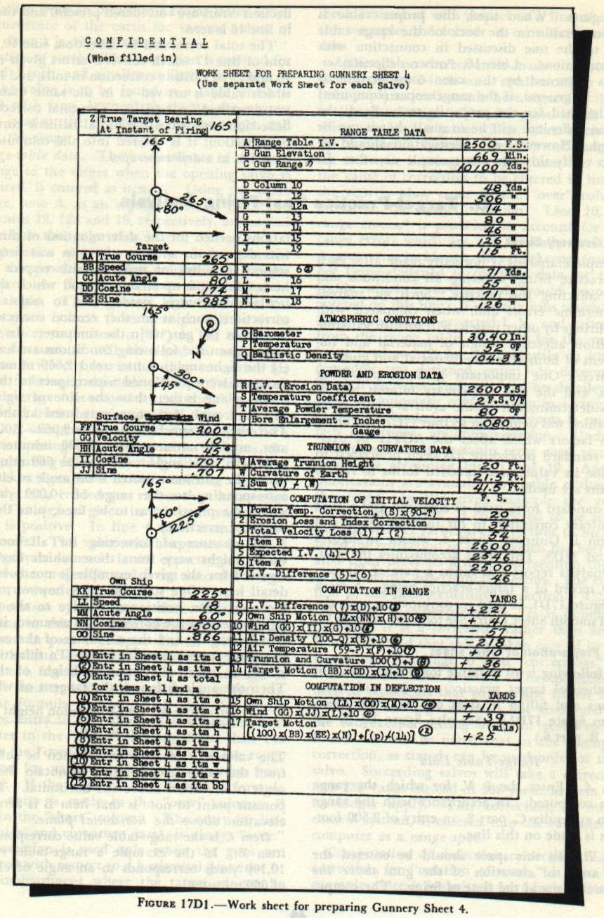
17D2. Preparation of work sheet
The following is an example for the first salvo of a hypothetical target practice, starting with computations and filling in data on the work sheet. Refer to figure 17D1.
Range-Table Data. Item A: Enter the I.V. for which the range table is computed (2,500 foot-seconds for the 5"/38 table). Item B: The actual angle of elevation of the gun above the horizontal plane at the time of firing. In the example, the sight-angle counter read 2,669 minutes; the guns were positioned with respect to the horizontal plane; and no erosion correctors were used at the guns. The entry in item B is therefore 2,669 − 2,000 = 669 minutes. Item C is the range-table value corresponding to item B (10,100 yards for 669 minutes elevation). Items D through N are taken directly from the proper columns of the range table, entering with the value of item C.
Atmospheric Conditions. Items O and P (30.40 in. and 52° F.) are surface readings from ship's instruments. Item Q, ballistic density, is entered from measured aloft data when available.
Powder and Erosion Data. Item R is the initial velocity used as a basis for velocity loss (2,600 f.s. for a new 5"/38 gun). Item S is the temperature coefficient (2 f.s. per degree F.). Item T is the average magazine temperature. Item U is the bore enlargement obtained from star gaging or ESR records.
Target, Wind, and Own-Ship Data. Three spaces are provided on the work sheet for indicating by vectors the target, wind, and own-ship motion relative to the true bearing of the target. The components in range and deflection are computed from the acute angles between each motion vector and the line of true target bearing. Target motion toward own ship decreases range; away from own ship increases range.
Computation of Initial Velocity. Item 1 is the error in I.V. due to variation in powder temperature from 90° F. (using sign convention: if temperature exceeds 90° sign is minus). Item 2 is always a velocity loss from erosion. Item 3, the algebraic sum, is the total velocity correction from standard. Items 4 and 5 give the expected initial velocity set into the rangekeeper.
Computation in Range and Deflection. Items 8 through 14 for range and items 15 through 17 for deflection are filled in accordance with the instructions on the work sheet, using care in selecting the proper signs so that correct values of expected range and deflection result.
17D3. Computation of arbitrary correction to hit (range)
After completion of the work sheet for Sheet 4, actual computation of the sheet will be undertaken. Refer to figures 17D2 and 17D3.
Item a, “number of guns,” refers to the number of guns actually fired. Item b, “number of cold guns,” is entered the number of guns firing their initial round since last cleaned and oiled. Items d through n are obtained from the work sheet, with the proper signs.
Item o, the expected range, is the gun range corrected for all known variations from standard range-table conditions which affect the projectile in flight, plus trunnion height and earth's curvature. Item p is the navigational range at the instant of firing. Item q is target motion during time of flight. Item r, the error of MPI, represents the actual difference between the position of the target at the instant of the fall of the projectiles and the mean point of impact. Item s is the actual range to the point of fall. Item t, therefore, represents the otherwise unaccounted-for errors — the average value of which for several complete practices may be used as ACTH in range.

17D4. Computation of arbitrary correction to hit (deflection)
Item u is the difference between the midpoint of the deflection scale and the actual scale reading. Items v, w, and x are taken from the work sheet with proper signs. Item z includes a conversion from yards to mils at the actual range. Item aa, the expected deflection, consists of the deflection used, corrected for drift and for those variations from standard range-table conditions which affect the projectile while it is in the air. Item bb is obtained from the work sheet. Item cc is the error of the MPI in mils. Item dd is the actual deflection of the MPI in mils. Item ee, the ACTH in deflection, is obtained by subtracting item aa from item dd. These two values — ACTH in range and deflection — represent the errors otherwise unaccounted for, to be used as the arbitrary correction to hit in subsequent firings.
