
Chapter 18 of Naval Ordnance and Gunnery, Volume 2 — Fire Control covers the theory and practice of spotting — the application of corrections to gun-laying data to bring shots onto the target. Sections treat the laws of probability as they affect gunfire and dispersion, the duties and techniques of the spotter, and the principal methods of spotting used in surface, antiaircraft, and shore-bombardment fire.
A. Laws of Probability in Their Effect on Gunfire and on Spotting
18A1. Requirement
As the study of exterior ballistics has indicated, not all the factors which affect the flight of a projectile can be precisely evaluated in advance of firing. Even with the best fire control equipment available, experienced gun crews, and efficient fire control personnel, the opening shots may not hit the target. It is therefore necessary to apply corrections (or spots) to the initial firing data to bring the shots on the target. The corrections are applied to gun-laying data for subsequent rounds fired. This technique is called spotting.
18A2. Definitions
The following definitions relate to gunfire and to terms used in connection with spotting.
Salvo. A salvo consists of one or more projectiles fired simultaneously by the same battery at the same target.
Slow fire. Slow fire is that type of fire in which the fire is deliberately delayed to allow for the application of spots or to conserve ammunition.
Rapid fire. Rapid fire is that type of fire which is not delayed for purposes of applying corrections.
Continuous fire. Continuous fire is the firing of each gun without regard for the readiness of other guns in the battery. No real salvos exist in this type of fire, but a spotter may treat those shots which fall during an interval of a few seconds as a salvo for his purposes.
The MPI. The mean point of impact (MPI) is the geometric center of the points of impact of the various shots of a salvo, excluding wild shots.
Wild shot. A wild shot is a shot with an abnormally large dispersion in range, or deflection, or both. In general the dispersion of a wild shot is too great to have been caused by any of the accidental errors mentioned in article 18A3, and is considered as due to a mistake rather than an error. For example, a powder bag loaded with its ignition pad forward is a mistake and will probably cause excessive dispersion. Again, in pointer control, if a sight setter were to set a range of 15,000 yards instead of the correct range, 10,500 yards, the results would be considered a wild shot. In director control, an error in the train parallax correction or the roller-path inclination setting, both of which are applied at the individual turret, may have a similar result, as will become clear when these corrections are explained in chapters 19 and 21.
Pattern. The pattern of a salvo in range is the distance measured parallel to the line of fire between the shortest shot of the salvo and the longest shot, excluding wild shots. In deflection it is the distance measured at right angles to the line of fire between the shot falling or bursting farthest right and the shot falling or bursting farthest left, excluding wild shots.
Dispersion. The dispersion of a shot is the distance of the point of impact of that shot from the MPI of the salvo. Dispersion in range is measured parallel to the line of fire, and in deflection at right angles to the line of fire in a horizontal plane. Dispersion in range is positive when the shot falls beyond the MPI. Dispersion in deflection is positive when the shot falls to the right of the MPI. The algebraic sum of the dispersions in range (or deflection) of the several shots of a salvo must equal zero.
Apparent mean dispersion. The apparent mean dispersion of a salvo in range (or deflection) is the arithmetical average of the dispersion in range (or deflection) of the several shots of the salvo, excluding wild shots.
True mean dispersion. The true mean dispersion is the arithmetical mean of the dispersions in range (or deflection) of an infinite number of shots, all assumed to have been fired under conditions as nearly the same as possible and excluding wild shots.
Hitting space. The hitting space (in range) for a target is the distance behind the target, measured parallel to the line of fire, that a shot striking the top of the target will strike the horizontal plane through the base of the target. It includes the projection of the target's vertical height upon the plane of the water and the target's horizontal dimension in the line of fire (or depth). It may also include a distance in front of the target within which impacts are likely to produce underwater or ricochet hits on the target. The hitting space in deflection is the width of the target. The term “hitting space,” as usually used, refers to the hitting space in range.
Danger space. The danger space for a material target is the distance in front of the target, measured parallel to the line of fire, that the target could be moved toward the firing point, so that a shot striking the base of the target in its original position would strike the top of the target in its new position.
Straddle. A straddle is obtained from a salvo in range (or deflection) when, excluding wild shots, a portion of the shots of that salvo fall or detonate short and other shots of the salvo beyond the target (right and left, respectively, for deflection).
Error of the MPI. The error of the mean point of impact is the distance of the MPI from the target or other reference point such as the center of the hitting space, measured parallel to the line of fire for range and at right angles to the line of fire for deflection.
18A3. Accidental errors causing dispersion
The problem of spotting is complicated by dispersion. If a battery of guns is fired at the same instant with the same settings in range and deflection, the projectiles will not all land at the same point.
If the battery of guns were stationary and rigidly fixed in elevation and train, variations in range and deflection would be caused by: (1) differences in weight and temperature among individual powder charges; (2) differences in projectile weights; (3) variations in angles of projection — the axes of projectiles diverging, in varying amounts, from the continuation of the bore axis as they leave the guns; (4) differences in projectile seating, causing variations in density of loading and initial velocity; (5) differences in erosion among the several guns, with corrections not precisely made; (6) differences in droop among similar guns, and unlike variations in droop with temperature changes; and (7) variations in amount the gun mount will yield and irregularity in action of recoil mechanisms. These are sufficient to justify acceptance of the fact that, even under ideal conditions, dispersion in the points of fall of projectiles from several guns, or in several shots from the same gun, may be expected.
If this battery of guns be mounted aboard ship, and each be individually positioned by a pointer and trainer, the rolling and pitching, and the yawing, of the ship itself will further cause dispersion. The motion of the ship may cause the pointers and trainers of the several guns to misalign their sights on the target when the guns are fired. The same effect may result from failure to fire exactly simultaneously, causing different guns to fire at slightly different points in the roll, and thus at different velocities of roll. Director-controlled gunfire, although not subject to the same characteristic errors as pointer fire, is subject to its own set of characteristic errors. These are discussed in some detail in articles 18A11 through 18A15.
The errors mentioned above as characteristic of pointer fire, and many of those which are characteristic of director fire, come under the general classification of accidental errors. They are revealed by analyses of firings, and their effects are governed by laws of probability, as will be explained.
18A4. Determining the location of the MPI
The definitions in the above paragraph will now be illustrated by an example, representing a salvo from ten 5"/38 caliber guns fired at range 8,500 yards against a target 40 feet high, 600 feet long, and with a beam of 90 feet. The target is situated with its length at 90 degrees to the line of fire.
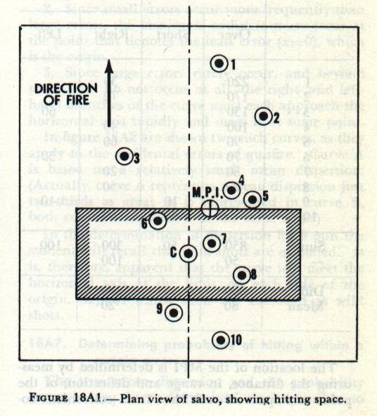
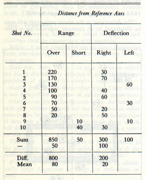
The danger space in range from column 7 of the range table is 40/20 × 25 = 50 yards. Since the “depth” is 90 feet, or 30 yards, the actual danger space is thus 50 + 30 = 80 yards. As discussed in article 17B11, for most battle ranges the value of hitting space is the same as that for danger space. Hence, in this case the hitting space can be considered 80 yards. Figure 18A1 represents the plan view of the target shown in terms of hitting space, an area 80 yards in range and 200 yards in deflection. The center of the hitting space is at C. The points of impact of the several shots are indicated by numbered dots and may be identified by referring to the adjacent table, which gives the location of each impact from the reference axes, in this case taken as intersecting at the center of the target's waterline.
The location of the MPI is determined by measuring the distance, in range and deflection, of the point of impact of each shot from convenient coordinate axes, and finding the mean of these distances. It is convenient to refer impacts to axes intersecting at the center of the target's waterline, as was done in the table. The mean of these distances is 80 yards over and 20 yards right, which locates the MPI 80 yards beyond and 20 yards right of the center of the waterline.
If we assume that the error of the MPI is its distance from the center of the hitting space, this is seen to be 40 yards over and 20 yards right. Inspection of figure 18A1, or of the table, shows that the pattern of this salvo is 260 yards in range and 130 yards in deflection.

18A5. Determining apparent mean dispersion
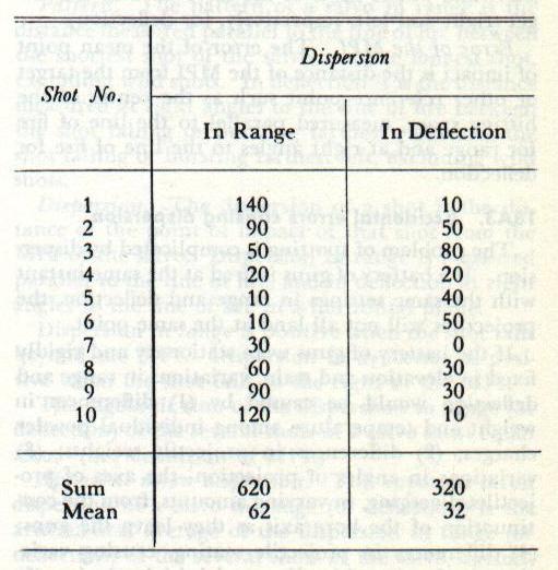
In determining the apparent mean dispersion it must be borne in mind that it is the arithmetical mean of the dispersions of the several shots, without regard to sign. The position of the MPI having been plotted, the several points of impact are now referred to the MPI to determine the individual dispersions and the apparent mean dispersion.
The apparent mean dispersion, based on 10 shots, is thus 62 yards in range and 32 yards in deflection. Being based on such a limited number of observations, it is not a true measure of the accuracy of fire. The true measure of the accuracy is the mean dispersion of an infinite number of shots, all fired under the same conditions as those under consideration, and is called the true mean dispersion. Although it is obviously impossible to measure the value of the true mean dispersion experimentally, a theoretical value is given by the relation shown in the table above.
The true mean dispersion, in the above case, is found by multiplying the apparent mean dispersion by 1.054. Hence the true mean dispersion in range, denoted by Dr, is 62 × 1.054 = 65 yards, and in deflection, denoted by Dd, is 32 × 1.054 = 34 yards.
18A6. Law of probability applied to dispersion
After determination of the true mean dispersion of shots fired by a battery of guns, the next step is the investigation of the manner in which the accidental errors, which resulted in this dispersion, will affect the chances of hitting a target, and how the control of a battery of these guns will be influenced by a knowledge of these errors.
In this study use is made of the laws of probability, which deal with the prediction of future occurrences on the basis of information gained from past occurrences. The laws of probability are the basis of the science of statistics, and may apply to almost any event or occurrence.
The law which pertains to symmetrically distributed accidental errors is known as the normal probability law. The accidental errors of gunfire follow a fairly symmetrical distribution, and this law is applied to them. It is based upon the following considerations: (1) positive and negative errors of the same size are equally probable, and hence will occur with equal frequencies; (2) small errors are more probable than large errors, and hence will occur with greater frequency than large errors; (3) very large errors will not occur (or, more specifically, very large errors will probably be due to mistakes and not be classifiable as accidental errors).
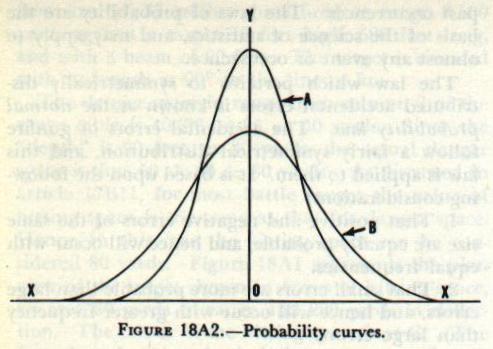
These considerations all pertain to the probable frequency of occurrence of errors of certain size and sign. Translated into a mathematical equation, the curve representing that equation will have the following characteristics (the abscissas measure the size of the errors; the ordinates, the frequency of their occurrence): (1) since positive and negative errors of the same size occur with equal frequency, the curve must be symmetrical to the right and left of the point that denotes zero error (x=0); (2) since small errors occur more frequently than large errors, the maximum ordinate must occur at the point that denotes the least error (x=0); (3) since large errors rarely occur, the right- and left-hand branches of the curve must each approach the horizontal axis rapidly and meet it at some point.
In figure 18A2 are shown two such curves, as they apply to the accidental errors of gunfire. Curve A is based on a relatively small mean dispersion (curve A represents a mean dispersion just two-thirds as great as is represented in curve B, both curves being drawn to the same scale). In the determination of dispersion for a gun the student will recall that wild shots are excluded. It is therefore apparent that the curve will meet the horizontal axis at the limit, on each side of the origin, beyond which shots are excluded as wild shots.
18A7. Determining probability of hitting within a certain error
The true mean dispersion and the probability curve having been determined, it is possible to determine the probability of hitting within a certain distance of the origin, that is, within a certain error, plus or minus. A table has been prepared in which this limit, denoted by a, is expressed as a percentage of the true mean dispersion D. The entering argument is a/D, the ratio of the particular error (±a) under consideration to the true mean dispersion D. The quantity P found from the table is the probability that an error not greater than ±a will occur, i.e., that the error will lie within the limits +a to −a.
It must be understood that this table may be used for the probability of occurrences in general, which follow the normal probability law. In the general case, a represents the error while D represents the index of precision as determined by past observations. (The index of precision refers to the degree of accuracy which has been observed in the past; in the case of gunfire it is the value of the true mean dispersion.)
From an inspection of the table two facts are readily apparent: (1) for a probability of 0.500, the error will lie between ±0.846D — or, the probability of hitting between limits separated by 1.692D is 50 percent; (2) the probability of hitting within limits of error equal to ±4D is 0.999. It follows that a dispersion greater than 4D will fall without the curve. In connection with problems in this course the student should consider a dispersion greater than 4D as due to a wild shot.
18A8. Probability of hitting when MPI is at center of hitting space
The case pictured in figure 18A1 will now be employed to illustrate the use of the probability table, in the case where the MPI is located at the center of the hitting space. If the entire salvo be shifted in range and deflection to bring the MPI to coincide with C, it will be seen that shots 4, 5, 6, and 7 are material hits, i.e., hits within the material target. The table will be employed to determine the percentage of an infinite number of shots which may be expected to hit this target.
The probability of hitting in range, Pr, is determined by entering the table with a value of ±a/Dr equal to ±40/65 = 0.62. (The hitting space being 80 yards in range, ±40 yards encompasses the hitting space. The true mean dispersion in range, Dr, from article 18A5, is 65 yards. The ratio will be carried to two decimal places.) The value of Pr is 0.379, to three decimal places.
In deflection the hitting space is 200 yards and the true mean dispersion in deflection, Dd, is 34 yards; thus ±a = 100 yards. ±a/Dd = 100/34 = 2.94, and the probability of hitting in deflection, Pd, is 0.981.
It is an axiom of the laws of probability that if an event is independently controlled by more than one set of conditions, the probability of its occurrence under all of these sets of conditions is equal to the product of the several probabilities of its occurrence under the several sets of conditions. Thus, in a pack of playing cards, the probability of drawing a king is 1/13, and the probability of drawing a spade is 1/4. The probability of drawing the king of spades is then the product of these two probabilities, or 1/52. In this case, the probability of hitting the target depends upon the probability of hitting in range and the probability of hitting in deflection. Therefore, the probability of hitting, P, is the product of these two probabilities, or 0.379 × 0.981 = 0.372. Then for a salvo of 10 shots about 4 hits should be obtained. (The fact that more or less than this number may be obtained on any one salvo is of no moment at this time, because these laws are based upon a great number of occurrences and do not directly apply to any one.)
Figure 18A1 also shows that the densest portion of the salvo is centered upon and relatively close to the MPI. In article 18A7 it was shown that one-half of the shots, or five in this case, should fall within ±0.846D of the MPI, or within 0.846 × 65 = 55 yards in range and 0.846 × 34 = 29 yards in deflection. In figure 18A1 it is seen that 5 shots are within this limit in range; 4 shots are within this limit in deflection, with 2 more just 1 yard outside the limit.
The above paragraph shows the importance of maintaining the MPI at the center of the hitting space. As the MPI moves away from the center, it carries with it the area of greatest density of impacts, and the probability of hitting falls off very rapidly. For comparison, the probability of hitting this same target will be determined for the case where the MPI lies just one-half pattern, or 130 yards, beyond the center of the hitting space.

Referring to figure 18A3, the center of the hitting space, which is represented by the shaded area, is at C. The MPI is 130 yards beyond and in line with C. In order to find the probability of hitting within the hitting space, in range, it is necessary first to determine the probability of hitting the total area ABCD, using ±a equal to 170 yards, which is seen to be equal to the error of the MPI plus one-half the hitting space, S'. This probability is denoted by the symbol Pr1. Next the probability of hitting within the area EFGH is determined using ±a equal to 90 yards, which is equal to the error of the MPI minus one-half the hitting space, S'. This probability is denoted by Pr2. Now, if Pr2 is subtracted from Pr1 the result will be the probability of hitting within area ABCD minus EFGH, or within the two areas ABFE and HGCD. These two areas are equal, so that the probability of hitting within the single area HGCD is one-half this result, or
Pr = ½(Pr1 − Pr2).
This problem will now be solved as explained above. True mean dispersion in range, Dr, as before, equals 65 yards.
For Pr1, ±a/Dr = 170/65 = 2.62; and Pr1 = 0.963.
For Pr2, ±a/Dr = 90/65 = 1.38; and Pr2 = 0.728.
Then Pr = ½(0.963 − 0.728) = 0.118.
But P = Pr × Pd. The value of Pd will not differ from the value found above, since the error of the MPI in deflection is zero.
Hence P = 0.118 × 0.981 = 0.116.
18A9. Spotting MPI to center of hitting space
The two cases illustrated in figures 18A1 and 18A3 will be analyzed to see what information may be obtained of interest to a spotter on shipboard. In the first case, with the MPI at the center of the hitting space, the laws of probability show that about four hits (i.e., 0.379 × 10) in range should be obtained in a 10-shot salvo. Therefore, about six shots will miss the target; and since the first consideration of the normal law states that positive and negative errors will occur with equal frequency, it follows that about three [(10 − 3.79) ÷ 2] of these misses will be “shorts.”
Probably the most common fault of spotters is the feeling that shorts are wasted, since it is so readily apparent that they have not hit the target, and that ensuing salvos must be spotted up until no shorts are seen. Consideration of relative sizes of pattern and hitting space will show, however, that if the MPI is to be anywhere in the hitting space, some shots must be observed short of the material target, even with the symmetrical shot distribution assumed in this discussion.
Again, remembering that the greatest density of impacts is grouped within a relatively short distance of the MPI (±0.846D), it is obvious that if no shorts are seen the MPI must be well beyond the center of the hitting space and, at any likely range, well outside the hitting space. Thus the greater part of the salvo, and particularly the densest portion of the salvo, is actually being wasted. Also, as the range increases, the hitting space decreases, the probability of hitting decreases, and the number of shorts which should be seen increases.
In the second case, the error of the MPI in range is one-half the pattern size. The MPI is 90 yards beyond the material target and the densest portion of the salvo, included within the distance ±0.846Dr, is entirely beyond the target. The probability of hitting in range is reduced from 0.379 (for error of the MPI equal to zero) to 0.118, or by more than two-thirds. These values clearly demonstrate the necessity of spotting the MPI to the center of the hitting space, which in turn requires a considerable number of observed shorts.
An officer detailed to duties which include spotting should know the probability of hitting at various ranges up to the extreme range of his battery against the various types of target which might be encountered. This information will tell him the number of shorts which should be expected or striven for under all possible conditions.
18A10. Accidental errors causing shift of MPI
Another phase of the problem of interest to the spotter is a knowledge of the amount which the MPI's of successive salvos may be expected to vary in location. Since the MPI is the center of the points of impact, which are the results of unpredictable accidental errors, it is logical to suppose that no two salvos will be exactly alike. Or, since successive shots from the same gun, fired under the same conditions, may be expected to vary, the MPI's of successive salvos will also vary.
The MPI of 100 shots (although fired as 10 salvos of 10 shots each) is the geometrical center of the points of impact of these 100 shots. The MPI's of the individual salvos will differ from this aggregate MPI by varying amounts which, however, are still in accordance with the normal probability law. The distance each MPI is located from the aggregate MPI is the dispersion (in range and deflection) of that MPI. The arithmetical mean of the dispersions of several MPI's (with respect to the aggregate MPI) is called the mean dispersion of the MPI. This value may be obtained by the equation:
While the spotter cannot estimate the MPI of a salvo with any such degree of accuracy, he should expect the number of shorts seen on successive salvos to vary as the MPI's of these salvos move about the center of the hitting space. He should therefore not be too quick to spot when only one or two salvos seem to wander off the target during a string that is, in general, satisfactory.
18A11. Control errors
The only accidental errors so far considered have been those which affect individual guns of a battery. These are known as gun errors and should be distinguished from another class of error which affects the battery as a whole. These are known as control errors and include those made in range-keeping, transmitting of data to the guns, and, in director fire, director pointing errors. They are not reflected in increased pattern sizes (i.e., increased dispersion among the guns) but in increased dispersion of the MPI's themselves.
Before the first salvo is fired at a target, as many effects likely to cause error of the MPI as practical are accounted for. If this salvo has an error of MPI, it is the result of control inaccuracies. There are four general control inaccuracies which may cause error of the MPI: (1) rangekeeper set up with incorrect range, courses, and speeds; (2) ballistic corrections based on conditions not existing at the time of firing (initial velocity, wind, air density, and others); (3) battery not properly aligned with director; (4) indeterminate errors (Class B and personnel errors).
18A12. Incorrect rangekeeper set-up
The present range to the target is valid only to the extent that its measurement is accurate. An error in this basic range measurement is directly registered as an error in MPI.
Measurements of own-ship course and speed usually are reasonably accurate, but any inaccuracies result in an error of MPI.
The determination of the target's course and speed is made directly from the spotter's estimate of target angle and speed, from the radar plot in CIC, or by rate controlling. Correct values of these two variables are most difficult to determine; they are the chief cause of an incorrect rangekeeper set-up, and thus the chief source of MPI error.
18A13. Inaccurate ballistic corrections
The computer determines corrections necessary to compensate for variations from standard conditions. If the determination of these corrections is based on incorrect values of ballistic wind, initial velocity, air density, and others, the total ballistic correction will be in error and will result in a corresponding error in MPI.
18A14. Improper battery alignment
The alignment referred to here is not intended to mean improper alignment between the guns of a battery. Such misalignment results in greater dispersion and larger pattern sizes, but does not materially affect the error of the MPI of a salvo. The improper alignment referred to here means the misalignment which may exist between the controlling director and the battery as a whole. This type of error is generally caused by failure to director-check the battery and all directors. Thus, a battery which is aligned with one director is not necessarily aligned with another which may be in control. Frequent director checks can assist in elimination of this cause of error in MPI.
18A15. Indeterminate errors
One of the two classes of indeterminate errors results from the fact that some of the computations by fire control instruments are only approximations of the true solutions. They are acceptable because they are susceptible of easier mechanization. These approximations result in Class B errors, which are small for normal ranges and therefore cause minimum error in MPI. However, at extremely short or long ranges the errors may become large, depending upon the instrument concerned, and thus may seriously affect the MPI. When Class B errors are known to be large, they are not admissible as accidental, and steps must be taken to make correction for them.
The other class of indeterminate errors is assignable to control personnel. An example would be the director pointer or trainer being off the point of aim when the salvo is fired. Only training and experience can prevent the occurrence or reduce the magnitude of such mischance. Small errors of this type merely cause a slight shift or dispersion of MPI and should not be corrected by the spotter. The director operator should inform the spotter of large discrepancies in the point of aim, in order that the spotter may distinguish this error from others.
18A16. Summation of errors
During actual firing a spotter cannot analyze each fall of shot to determine the exact geometrical MPI of a salvo. Splashes last only a matter of seconds, and the firing situation is probably changing even during that short interval. The spotter must have previously analyzed all probable errors and the reasons for them. This knowledge, coupled with practical training, will enable him to make instant and intelligent decisions as to the proper correction or spot necessary to hit the target.
To summarize, the general errors attending shipboard gunfire are:
(1) Accidental gun errors causing dispersion of shots. These errors are only compensated to the extent of achieving desired pattern sizes. Most of the errors are eliminated by careful design, frequent checks of battery alignment, normal upkeep of the battery, and the training of gun crews.
(2) Accidental gun errors causing a shift in the MPI of successive salvos. The shift in range is usually small; a noticeable shift in deflection is observed when using radar aim.
(3) Control inaccuracies causing error of MPI. It is the primary duty of the spotter to “spot” the corrections in range and deflection necessary to bring the MPI of a salvo to the desired point of impact. He should recognize the first two classes of errors in order to spot the error of MPI caused by control inaccuracies.
B. The Spotter
18B1. General function of the spotter
The primary function of the spotter is the correction of range and deflection errors of the MPI so as to bring the shots on the target, or, in other words, to establish the hitting gun range and deflection. The basis of these corrections is his own observation combined with those of the fire control radar operator. As a rule, in good visibility the spotter will estimate the necessary deflection correction, and range corrections will be obtained from the radar. Under unfavorable conditions both range and deflection corrections will be obtained from the radar. Prompt and accurate correction of initial errors may be the deciding factor in a naval engagement.
In the event of radar failure, optical spotting must be relied upon for all corrections necessary to establish the hitting gun range and deflection. Therefore in the initial discussion of the spotter's problems, it will be assumed that radar is not available.
18B2. Other functions and duties
The spotter's detailed duties and spotting procedures are prescribed in the ship's battle bill and fleet doctrinal publications. Included are the following important duties:
(1) Search for and locate the enemy. (2) Describe the enemy forces (number of ships, bearing, etc.). (3) Estimate all values for the initial rangekeeper set-up (enemy speed, target angle, and range). (4) Notify Plot and Control of any changes of target angle, target speed, and enemy deployment. (5) Keep Conn and Control informed of the tactical situation.
18B3. Visual estimation of target course and speed
The spotter who can estimate target angle and target speed with fair accuracy will greatly assist the rangekeeper operator in arriving at an early solution of the problem, and also aid him in checking the rangekeeper set-up. On the other hand, if the spotter's estimates are inaccurate the rangekeeper operator will have to make many changes.
To estimate target angle the spotter must know the structural details of all likely targets. Silhouettes and scale models of all probable targets are furnished each ship. The spotter should study the details of these visual aids, not only for the purpose of recognizing the enemy, but also for estimating target angle. In estimating target angle, the spotter should make use of prominent objects such as bridges, breaks in the deck, stacks, masts, and other features. By observing the opening and closing of the apparent distance between such details, the spotter can estimate the angle the enemy ship makes with the line of sight.
Target speed can at best be only roughly estimated. Here again, knowledge of enemy ships is valuable, particularly in the case of maximum speeds. If in line of battle, target speed may be estimated as about 1 or 2 knots less than the maximum speed of the slowest ship in the formation, considering any damage reports which may have been received. The best speed estimates can be made only by men who have had extensive training and experience. The aids used by a spotter in a direct estimation of target speed are smoke from the stacks, bow wave, and stern wake.
18B4. Visually spotting error of MPI in deflection
Correcting the deflection is extremely important not only for hitting but also because, in long-range surface fire, it is difficult to spot in range if the deflection error is excessive. A salvo which is widely off a target should first be spotted in deflection, and the succeeding salvo spotted in range. In estimating deflection spots, the estimated target width in mils should be used as a guide. Also, telescopes, binoculars, or other optical devices fitted with mil scales furnish a suitable means of estimating deflection errors.
With a high-speed target, the spotter should bear in mind that the apparent MPI in deflection should be held abaft the point of aim in order to allow for the travel of the target while the splashes are forming. In other words, it must not be assumed that full splashes form instantaneously at the impact of a salvo. The time lag is only a few seconds at most, varying with the caliber of projectiles, but is sufficient to allow considerable movement of a high-speed target.
18B5. Visually spotting error of MPI in range
One of the most common mistakes made by the untrained spotter is to underestimate the amount of the range error at long ranges. This is due to the fact that a given range error will subtend a much smaller angle at long ranges than it does at short ranges. However, with good visibility and a spotting height of 120 feet or more, the error of MPI can usually be estimated with reasonable accuracy at ranges up to 15,000 yards. This is accomplished by observing the position of the bases or slicks of the splashes relative to that of the waterline of the target.
Experience in determining range error can be gained during target practice and by individual practice on a spotting board, which stimulates the appearance of splashes relative to the target as viewed from a spotter's station. Spotting diagrams are used in conjunction with such training to indicate the relative displacement of a salvo from the target and to estimate ranges. Figure 18B1 shows a typical example for spotting height of 100 feet and target heights of 10 feet, 20 feet, and 30 feet. Such a diagram is constructed by means of dip curves for the particular height of a spotting station. Range lines are drawn at intervals of 500 or 1,000 yards, from minimum range to that of the horizon. These range lines represent angular distance below the horizon at which any object would appear from a height of 100 feet, if observed on the range lines so marked. The distances between the range lines represent the apparent range differences as viewed by an observer at the spotting height for which the diagram was constructed.
A study of figure 18B1 makes it evident that salvo A is short of the imaginary extension of the waterline of a target at 12,000 yards by about 500 yards. However, the error of a salvo fired at a target at 19,000 yards is not so apparent. The 500-yard error of such a salvo (indicated on the diagram as salvo B), appears as little or no error in apparent distance from the extended waterline of the target. Thus it can be seen that for shipboard spotting at such a range, the splashes must be in line with some portion of the target before the spotter can reasonably tell whether the salvo is over or short, to say nothing of estimating the amount of the error. In addition to its use for estimating range and range errors, the spotting diagram shows the number of mils a given target length will subtend at any given range. For example, in figure 18B1 a 600-foot target will subtend 20 mils at 10,000 yards range.

C. Methods of Spotting
18C1. Spotting terminology
It is important that the proper terminology and order of spots be observed by the shipboard spotter.
The surface problem. For surface fire, only range and deflection are spotted. The correction necessary to bring the MPI on the target is given in the following terminology and order: (1) deflection correction — RIGHT or LEFT, in mils; (2) range correction — ADD or DROP, in yards. Where no correction is necessary, the designation NO CHANGE is used. Typical examples of spot transmissions by telephone are RIGHT 10, ADD 1,000, DROP 500.
The AA problem. For air targets, corrections to bring the burst on the target are needed in three dimensions. Even well-trained personnel find it almost impossible to estimate errors rapidly in three dimensions. AA spotting is therefore generally ineffective and is usually not attempted except in cases of obvious constant system errors. The proper terminology for spotting in the AA problem is: (1) deflection correction — RIGHT or LEFT, in mils; (2) height-of-burst correction — UP or DOWN, in mils. Deflection and elevation spots will normally be made by the control officer; range spots will be made by the rangefinder or radar operator.
Naval gunfire support. In shore bombardment, as in AA fire, spots in three dimensions may be necessary. The terms are the same as in the preceding paragraph, but the units are not the same. When naval guns are used to support landing operations, joint forces are involved. The Navy, Army, and Air Force have a standardized spotting terminology for joint operations which will differ from the above, in that all corrections are spotted in yards. At the rangekeeper or computer, deflection and elevation spots must be converted to angular units before being applied to the computer.
18C2. Methods of spotting
It is evident from the preceding discussion that certain methods of spotting and certain other techniques to assist in the control of gunfire must be employed by the shipboard spotter in the difficult problem of estimating the MPI error in range. It must be borne in mind that these methods and techniques are but general guides and are in no way intended to replace or abrogate actual procedures which are laid down in detail in Fleet and Force doctrines. Such doctrines must be perfectly known and rigidly followed by the spotter under all conditions.
Subject to the foregoing qualifications there are two methods of spotting: (1) the direct method; (2) the bracket-and-halving method. There are also three other techniques used in the control of gunfire which are closely related to spotting and must be discussed at this point: (1) ladders; (2) barrages; (3) tracer control. The use of any of the above methods or techniques is determined by the type of battery firing, the type of target, the range, and the visibility.
18C3. Direct method
Spotting by the direct method is, as its name implies, the spotting of salvos (splashes) direct to the target. This is the most desirable procedure, but its use is very limited. For reasonably accurate spotting at a range of 15,000 yards, a spotting height of 120 feet is required. It is also necessary that the splash be relatively close to the target, and that the rangekeeper set-up be fairly accurate. These considerations limit this method to main-battery fire at relatively short ranges.
A thoughtful analysis of the problem with reference to the spotting diagram in figure 18B1 reveals that the greatest limitation of the direct method is the matter of range. Deflection spots can be made with equal accuracy at any visible distance. If, then, air spots are available, and the plane spots in range with the ship spotting in deflection, the direct method can be used by the main battery at any range at which a portion of the splash is visible to the shipboard spotter. Air spotters cannot spot accurately in deflection unless they have a line of sight containing the firing ship and the target. Radar spotting is usually direct, even at considerable ranges.
18C4. Bracket-and-halving method
The bracket-and-halving method is used at long ranges by the main battery when no air or radar spot is available. At great distances it will be impossible to tell if a splash is short of or over a target, unless the two are in line. If the splash and target are not in line, or if the splash does not line up with a ship in the formation whose range is approximately that of the target, the first spot is made in deflection only. When target and splashes are in line in deflection, a range spot is made in such a direction and amount as to “cross” the target definitely. The direction of the next spot is reversed, and the size of the spot is cut in half. This “halving” is continued until a straddle is obtained, at which time it may be appropriate to shift to rapid salvo or to continuous fire. The spot should not be reduced below pattern size. Once a straddle is obtained, centering deflection spots only should be made, as long as the spotter is sure he has both short and over splashes. If, however, over splashes are obscured by the target or by shorts, every third or fourth salvo should be fired with an add spot of one pattern size, so as to lift the entire salvo over the target. Only thus can the spotter know his straddles were not all shorts in reality.
18C5. Ladders
When ranging is difficult and visibility poor because of fog, smoke, or darkness, the use of ladders is of considerable assistance to a spotter. Ladders are not particularly adaptable to fast-moving targets. Fire is deliberately opened short, and succeeding salvos are fired so as to approach the target in steps not less than pattern size. As soon as the target is crossed, the steps are reversed and halved until the target has again been crossed. After a straddle has been attained, a rocking ladder may be used in conjunction with slow timed fire or with rapid salvo or continuous fire. This consists of moving the pattern back and forth across the target by small arbitrary successive spots such as +100, 0, −100, . . . introduced at the computer or rangekeeper. It has the effect of increasing the pattern size, which may be valuable when firing against a target capable of rapid maneuvering. When this method is used, care must be taken to make correcting spots only when the zero salvos of the ladder series fall. The rocking ladder can be used in conjunction with air or radar spotting, so long as the spotter is kept informed that this technique is being used.
18C6. Barrages
The barrage method of control consists of placing a zone of fire short or over the target, according to whether the target is closing or opening range. The gun range is kept constant until the target passes through the zone, and is then lowered or raised as necessary to force a second passage through the barrage, continuing the movement of the barrage as may be necessary. This system is used by smaller-caliber fast-firing batteries against light, fast-moving targets. It is the spotter's function to determine when the barrage should be shifted, and in which direction and how much it should be moved.
18C7. Tracers
The tracer method of control consists of spotting shots by noting the error as the tracer passes the target. It is used chiefly in spotting machine-gun fire. This method may also be used in addition to others in spotting larger-caliber projectiles (i.e., 5"/38 cal. or larger), particularly at short ranges. At longer ranges, tracers are of doubtful assistance to the spotter, because of the difficulty in keeping them in sight or in judging when they pass the target. Under certain light conditions the tracers cannot be seen clearly, and should not be relied upon except for short-range firing.
18C8. Short-range spotting
Spotting the fall of shot at very short ranges differs from other spotting problems in that range errors are not difficult to judge. However, in determining deflection errors at short ranges, consideration must be given to the travel of the target and the spotter's position relative to the line of projectile flight. For example, with the firing ship and target on opposite courses, target to starboard, a shot fired with correct deflection but long in range will appear to the spotter to be in error to the left of the target. Special short-range splash diagrams are constructed as an aid to the spotter in this type of firing; instructions for their preparation and use are available in publications carried by all ships.
18C9. Radar spotting
Radar, using Type B presentation, gives accurate range errors under any visibility conditions. Therefore, it has completely replaced visual spotting as the primary means of determining range errors. Bearing discrimination by radar has become sufficiently accurate to justify its use as the primary means of deflection spotting. However, normally in a day action under favorable visibility conditions the following procedure is followed in spotting: (1) when splashes can be unmistakably identified on the radar screen, direct radar spotting in range is employed; (2) when splashes can be seen visually, the top spotter on the ship employs direct spotting in deflection; (3) any available aircraft spots are used as a check. In the event of a night action, or action under conditions of reduced visibility, radar will normally be employed for both range and deflection spots.
18C10. Pyramiding spots
Spot pyramiding is the application of a new spot before the effect of a previous spot has had time to become apparent. It can occur only at rapid fire, when the interval between shots or salvos is less than the time of flight plus the spotting interval. In that case, when a salvo lands there are one or more other salvos in the air. Suppose the spotter makes a spot on the salvo which has just landed. This spot is applied and a new salvo is fired. Then one or more of the salvos which were already in the air lands, and the spotter, forgetting that his previous spot has not had time to show its effect on the fall of shot, spots again. This spot is applied to the next salvo fired, with the result that this salvo is over-corrected and will probably miss, as will subsequent salvos until the spotter sees his mistake and spots back again to remove the pyramided spot.
In order to help the spotter avoid pyramiding, the time-of-flight signal mechanism is used. This mechanism may be incorporated in the rangekeeper or may be in the form of a separate time-of-flight clock. It is operated by the rangekeeper operator or an assistant, who presses a button when the salvo on which a spot is applied is fired. Just before the salvo lands the mechanism sounds a buzzer which informs the spotter that a spotted salvo is about to land. When this system is used, the spotter, after making a spot, waits for the buzzer before making another spot.
Spot pyramiding is a very common fault and has a disastrous effect on accurate control of fire. Every means available must be used to prevent it, and these means must be carefully and correctly operated. If they are improperly operated, they may cause worse errors than they are designed to prevent. For example, if the time-of-flight mechanism operator forgets to press the button for a spotted salvo, and the spotter waits for it, he may continue to wait after it becomes apparent that his previous spot was incorrect. In such a case the operator making the mistake should advise the spotter of the situation as soon as he himself realizes it. Some ships have a Spot Coordinator, located in the plotting room, who is responsible for the prevention of pyramiding as well as for the coordination of radar, shipboard visual, and air spots.
When modern fire control systems are being used to solve the fire control problem, the process described in subsequent chapters as rate control is used to make constant corrections to the solution. If spots are applied at the same time as rate control corrections, the effect is the same as pyramiding of spots. This provides an additional reason for not ordinarily attempting to spot bursts in antiaircraft fire.