
A. Rockets and the Rocket Principle
11A1. Definitions
A rocket is a missile propelled by the escape of gases produced from the burning of solid, liquid, or gaseous propellants completely contained within itself. A true rocket by definition does not, for example, use atmospheric oxygen to burn its fuel.

Figure 11A1 shows the external appearance of one type of rocket. The head of this rocket contains a high-explosive charge and a nose fuze to initiate detonation. The motor contains the combustion chamber, and houses the propellant charge. Hot gases from the combustion chamber issue from a nozzle at the after end of the assembly.
Rockets exhibit two characteristics unique in the field of propulsion: (1) the propulsive force delivered is independent of atmospheric air, and thus the rocket may be propelled through empty space, and (2) the propulsive force is unaffected by the velocity. One of the challenging problems in rocket design is to develop an acceptable degree of stabilization in flight. The rocket shown in figure 11A1 represents a spin-stabilized rocket.
11A2. History of rockets
Rockets were used in the Far East as early as the 13th century. In the first decades of the 19th century several western armies employed rocket projectiles with greater or lesser success, a notable incident in the history of our own country being the use of rockets by the British during the attack on Washington in the War of 1812.
But the military use of rockets languished after the middle of the 19th century, attention being diverted from them by improvement in guns and gunnery. Projectiles fired from guns proved to be superior to rockets in both range and accuracy. So for many years the employment of rockets was largely associated with pyrotechnic displays. During World War II, however, the development of military rockets underwent a considerable revival in the United States, Great Britain, Germany, and the U.S.S.R. Short-range rockets were developed for use against shore installations, ships, tanks, airplanes, and personnel. The Germans produced a long-range rocket missile known as the V-2.
11A3. Principles of rockets
A rocket motor is a metal tube that serves as a combustion chamber. The burning propellant generates hot gas, and the gas pressure within the combustion chamber rises quickly to some value determined by the amount and characteristics of the propellant and the size of the nozzle or nozzles. The gas exerts approximately the same outward pressure on each square inch of surface within the combustion chamber; however, the gas rushes out of the nozzle without exerting any force upon the area of the opening, but with exertion of full force upon the corresponding area at the forward end of the combustion chamber. Thus a net force or thrust acts in the forward direction. The magnitude of this force is roughly the area of the orifice in square inches multiplied by the internal pressure in pounds per square inch.
Fundamental to rocket propulsion, then, is the conversion of heat energy into kinetic energy by an adiabatic expansion. This poses two basic problems: (1) to generate gas under high pressure and at a constant rate — a problem of chemical reaction; and (2) to direct the high-pressure gases into a high-velocity stream — a problem of nozzle design. Pressure in a rocket motor depends largely upon the burning rate and escape rate. In the case of solid-fuel rockets, for example, the composition of powder, shape of grain, and rate of burning, which have important relationships to performance as discussed in chapter 2 and chapter 3, are also important factors in rocket design.
a. Rocket motors. The thrust of a rocket motor is an equal and opposite reaction to the expansion of gases discharged at the nozzle; and since the expansion of these gases is maximum in a vacuum, rockets function most efficiently in such a medium. Rocket motors contain all the essentials for functioning, and do not require atmospheric oxygen for combustion.
The function of the nozzle is to permit the hot gas produced by the burning ballistite propellant to flow out of the rocket motor, pushing the rocket along as it goes. The shape of the nozzle determines the characteristics of gas flow, and hence has much to do with how efficiently the gas flow propels the rocket. Gas flow must be smooth (nonturbulent). For a smooth, controlled trajectory, it must produce thrust along the long axis of the rocket. And the nozzle must be designed to develop every possible bit of thrust from the flow.
By tapering the rear of the chamber so that it narrows smoothly toward the nozzle aperture, a smooth, nonturbulent flow of escaping gas is created. This tapered section forms the forward half of the nozzle. The tapered extension, forming the after end of the nozzle, which leads outward from the nozzle aperture, forces the escaping gas, as it expands, to furnish additional (about 33 percent) forward thrust. (Fig. 11A2.)
Many rockets have a number of nozzles, rather than just one. The same principles apply there.

The rocket MOTOR TUBE contains the propellant charge and igniter. It is a combustion chamber in which the propellant is burned to provide the motive power (hot gases) for the rocket. It generally threads to the rocket or an adapter in the base of the head, and is usually shipped separate from the head. The diameter of the motor is less than that of the head in some rockets; in others its diameter is about the same as the head’s.
The IGNITER contains black powder loosely packed, and an electric SQUIB with a low-resistance bridge wire running through a match composition.
All present types of rocket motors are initiated electrically. As figure 11A3 shows, the firing impulses may be transmitted either (in aircraft rockets) by a pigtail lead from the rocket plugged into a source of firing current, or (in surface-launched rockets) by contact surface on the shroud surrounding the rocket’s tail.
Most Navy rockets use either (fig. 11A4) a solid cruciform grain or a cylindrical grain with an axial hole and radial perforations. The latter, often used in Navy ground or shipboard mounted rockets, is characterized by three ridges spaced 120° apart and running longitudinally along the grain. The cruciform grain, usually found in Navy aircraft rockets, in section is a symmetrical cross. If all of the exterior surface of this grain were permitted to burn, there would be a gradual decrease of area, and the burning rate would be regressive — that is, the rate of gas production would decrease as the grain continued to burn. Since a uniform burning rate is desired, a number of slower burning plastic strips or INHIBITORS are bonded to certain parts of the area exposed on the outer curved ends of the arms. These slow the initial burning rate, and gas production rate is approximately uniform as long as the grain burns.
Hollow cylindrical grains have inherently uniform burning rates and usually require no inhibitors.
Grain sizes vary according to the motor in which they are to be used. Most use only a single grain, but some may use up to four.
The grid is a metal piece near the nozzle which supports the propellant grain so that sufficient clearance is allowed between the grain and the nozzle to permit a free flow of gas through the nozzle. Without the grid, the grain will move aft, blocking the nozzle and causing excessive pressures to build up in the motor.
Tail fins provide stability in flight, prevent tumbling, and ensure head-on impact. During burning, the action of the air against the fins tends to resist side forces of the nozzle and to improve the accuracy of fire. When there is a tail shroud around the fins, it supports the rear end of the rocket in the launcher.
Most newer shipboard-fired rockets are SPIN-STABILIZED; that is, their nozzles are canted to exert torque as well as forward thrust. The result is that the rocket spins like a gun projectile in flight. Such rockets, of course, have no fins. Since spin begins as soon as the propellant starts to burn, the stabilizing effect begins as soon as sufficient thrust is developed to launch the rocket.
Aircraft rockets are fin-stabilized designs. (To save space, folding fins that open on launching are often used.) Fin stabilization is poor when a rocket is launched at zero or low air speed (as is the case on surface craft); in aircraft, however, the plane’s air speed ensures good stabilization at the instant of launching.
Rockets have been designed with canted fins, to produce spin. This kind of design is, however, subject to the drawbacks common to other finned rockets.

b. Rocket heads. As previously noted, the head of a conventional rocket contains a high-explosive charge capable of being detonated by action of a fuze or fuzes. Use of centrifugal force and setback to arm fuzes, as in gun projectiles, is not universally applicable to rocket fuzes. In part, this is because rockets accelerate at a lower rate than do gun projectiles; moreover, with fin-stabilized rockets no centrifugal forces are available. For these reasons various other devices are employed to arm rocket fuzes. The fuzes of some antisubmarine rockets, for example, are armed either by hydrostatic pressure or by rotation of a propeller after travel of 15 to 20 feet in the water. When armed, such rockets detonate upon impact with any solid object. Several methods have been utilized to arm the fuzes of barrage or bombardment rockets so that they will detonate upon impact or after a predetermined delay. In one type of nose fuze, arming depends upon rotation imparted to a small propeller as the rocket moves through the air. A base-detonating type is armed by a mechanism that is actuated by pressure in the rocket motor during burning.
On the other hand, fuzes used on spin-stabilized rockets may be similar to the fuzes of gun projectiles, since centrifugal force is present.
c. Rocket launchers. Modern rockets are launched from various types of launchers, which in essence are mechanisms designed to point the rocket in the right direction and to actuate or ignite the motor. One significant fact about launching is that there is little or no recoil. The forward momentum given to the rocket is balanced by the rearward escape of propellant gases. Therefore, a very large total weight of “pay load” may be fired from boats, airplanes, or other conveyances which could not possibly withstand the recoil shock incident to firing equivalent projectiles from traditional types of larger guns. This is why the development of aircraft rockets, to cite one example, has been so significant. Inability of aircraft structure to stand up under the recoil shock of conventional-type guns had long been a limiting factor in aircraft armament. Until the rebirth of military rockets occurred, the largest projectile fired by most aircraft guns weighed only 2 or 3 pounds. The modern rocket-firing plane, however, is capable of launching rockets which weigh over 1,000 pounds.
It also is noteworthy that many rocket launchers are relatively light in weight, simple, inexpensive, and more readily replaceable than comparable guns. On the other hand, much more propellant is required to bring a rocket up to a given velocity than is the case with a gun projectile. Moreover, rocket fire (with conventional short-range rockets) launched from the ground or from the deck of a ship compares unfavorably in accuracy with gunfire.
Shipboard rocket launching devices always have a tube or rail which supports the rocket until firing, and guides it during the critical initial portion of its trajectory. This is necessary because, especially with fin-stabilized rockets, the stability of the rocket is relatively poor until it attains a fairly high air speed.
On fixed-wing aircraft, as has already been explained, fin stabilization of rockets is effective at the instant of launching because of the plane’s air speed. Rocket launchers in aircraft are therefore merely supports which hold the rocket until launching, and then release it as the propellant is ignited. These are called “zero length” launchers.
Shipboard launchers may be of “repeater” design to fire rockets successively at short intervals from a magazine or loading device. Electrical contact to the rocket’s squib in such launchers is made through a set of contactors which rub against insulated metal contacts on the rocket. In aircraft launchers, only one rocket is fired per launcher per flight. The electrical connection from plane firing system to rocket is made through pigtail leads and plugs, which part upon firing.
11A4. Rocket trajectory and stabilization
Mention has been made of the fact that conventional rockets are less accurate than gun projectiles. One reason for this is that gun projectiles are guided by the gun bore during the entire period in which the propellant is burning and maximum velocity is being attained. A rocket, on the other hand, is guided by its launcher, if at all, during only a very small portion of the time that its propellant burns; in all cases, maximum velocity of the rocket is attained after it has left the launcher, and in some cases after the rocket has passed through hundreds of feet of free flight. In addition, the center of gravity of a gun projectile remains fixed in position in relation to the projectile while the latter is in flight, whereas the center of gravity of the rocket necessarily shifts in relation to the rocket as the fuel in the motor is consumed.
After a rocket has attained maximum velocity, it may traverse a trajectory similar to the path traversed by a gun projectile. On the other hand, it is possible to place lifting surfaces (wings) on the rocket head, which will cause the missile to follow a glide path rather than a purely ballistic path, once acceleration is completed.
The older type of rockets which came into widespread use during World War II were fin stabilized. Such rockets have the advantage of being relatively simple to manufacture, but are likely to prove somewhat cumbersome in handling, launching, and stowing. It may be pointed out, however, that fin stabilization is the type associated with a glide path of flight, and that stabilizing fins, with proper adaptation, may be used as rudders and elevators in controlling the path of flight. These facts take on special significance when we consider the potentialities of guided missiles.
Spin stabilization has also been used extensively in the case of rockets. A spin-stabilized rocket, like a gun projectile, tends to maintain a relatively stable course because of the gyroscopic effect resulting from its rotating motion, which in part counteracts forces that otherwise would produce deviation in line of flight. As a case in point, one type of 5.0-inch spin-stabilized rocket developed during World War II had a nearly flat trajectory at short ranges, and rotated at about the same or even higher speed than a 5"/38 caliber projectile.
In a gun projectile, rotary motion or “spin” is imparted by rifling of the gun barrel. Spin-stabilized rockets, however, achieve a spinning motion because they have several nozzles, slightly canted in position. Since fins are absent, such rockets can be relatively compact, which makes for greater convenience in handling, launching, and stowing. The degree of stabilization may also be considerably greater than that of fin-stabilized rockets. The old fin-stabilized 4.5-inch barrage rockets, for example, had a dispersion of from 20 to 40 mils, whereas the comparable figure for spin-stabilized rockets is about 20 mils. When fired forward from airplanes, fin-stabilized rockets achieve a much better performance.

It therefore is evident that the accuracy of conventional-type rocket fire is not on a par with the accuracy of gunfire. Rockets, however, have proved to be extremely valuable weapons for special purposes. Examples include the employment of rockets in antisubmarine attacks, and the saturation of enemy-held beach positions by rocket fire launched both from airplanes and from the decks of landing ships. Figure 11A5 shows barrage rockets being launched from an LSI which is moving in toward a beach.
Fired from aircraft, dispersion of fin-stabilized rockets may be no more than 6 to 8 mils. Comparable dispersion of gun projectiles would be a single mil or less.
11A5. Rocket fuels
From the standpoint of fuels there are two general types of rockets: those incorporating liquid-fuel units as typified by the German V-2, and those incorporating solid-fuel units as represented by various barrage rockets.
In liquid-fuel rockets, the fuel and the oxidizer are carried in separate containers from which they are ejected into a relatively small combustion chamber where the propelling reaction takes place. A comparatively elaborate mechanism was used in the V-2 rocket to control this use of fuel and oxidizer; however, simple designs have been developed subsequently which permit the use of liquid propellants in high-performance antiaircraft rockets, less than 4-inch diameter, capable of developing high thrust for a short period of time. Also the fuel tanks of liquid-fuel rockets for guided missile propulsion can be so located that change in center of gravity is reduced to a minimum as fuel consumption proceeds.
Among the advantages of solid-fuel rockets is simplicity of design and operation. A single chamber serves as a container for the propellant and as a combustion chamber. Rate of gas production is controlled by the chemical composition of the propellant (especially by the ratio of the oxidizing agent to the fuel), by the operating pressure and temperature, and by the shape of the propellant charge and combustion chamber. In some cases inhibitors, consisting of slow-burning material attached to certain surfaces of the powder grain to delay combustion, are used. A disadvantage of solid-fuel rockets is the relatively great weight of the motor housing.
11A6. Naval uses of solid-fuel rockets
Rockets (but not guided missiles) fired by naval ships and aircraft are designated by head diameter in inches. (This is analogous to the caliber of gun projectiles.) The motor may be the same size as, or smaller than, the head, but never larger.
Several types of rocket of 3-inch and smaller caliber are used for practice firing, for targets at which other weapons can fire, or for signaling. Subcaliber rockets which fit into the launchers of larger types and are used as inexpensive substitutes for training purposes are also in this range of sizes.
Aircraft rockets intended for use against enemy targets or for other combat use are made in 3.5-inch, 5.0-inch, and 11.75-inch sizes. (Other sizes may be under development.) Rockets fired from surface craft are the obsolescent 4.5-inch fin-stabilized barrage rocket, several types of 5.0-inch spin-stabilized rockets, a 7.2-inch rocket designed for antisubmarine use, and the antisubmarine 12.75-inch rocket.
11A7. General safety precautions in handling and firing rockets
1. Review of ordnance instructions. Frequent review of ordnance pamphlets and the latest ordnance instructions pertaining to each piece of equipment should be made mandatory by all authorities in command of units afloat and ashore, wherever rockets are stowed, assembled, or fired.
2. Nozzle blast. It should be remembered that nozzle blast from a rocket motor is intensely hot. Small pieces of burning powder frequently are blown out of the nozzles and may be hard to extinguish. Steel sheathing is therefore used to protect decks and superstructure areas around launchers. Some launchers have blast deflectors for protection of the immediate area, while others are mounted slightly outboard, so that blast is directed into the water. It is obviously unsafe for any one to be directly in front of or behind a loaded launcher, or one that is being loaded. Personnel loading a launcher should always stand to one side of the path that would be taken by rocket or blast in the event of accidental or intentional firing. All personnel in the vicinity of a launcher should wear long trousers, and long shirt sleeves buttoned about the wrists.
3. Firing precautions. The firing circuit must be open at all times until the launcher is ready to fire. All extra rockets must be kept at a safe distance from loaded deck-mounted launchers. No personnel may approach a loaded launcher until the safety plug or firing key has been removed from the firing circuit. The fuze safety wire must be reinserted as soon as the safety plug or firing key has been removed, but not before. No test of the firing circuit may be conducted until all rockets have been removed from the launcher and placed at a safe distance. Naked lights, matches, or other flame-producing apparatus must never be allowed in the vicinity of rocket ammunition.
4. Fuzes. At no time are any personnel permitted to attempt disassembly of an armed fuze. Such a fuze must be disposed of.
5. Propellant grains. Under no circumstances may a propellant grain be removed from a motor. No surveillance tests are made of rocket propellants.
Other safety precautions are detailed in appropriate ordnance publications, in appendix A of this volume, and in the next section, on shipboard-fired rockets.
B. Rockets Fired from Surface Craft
11B1. General
As the previous article stated, the most important operational Navy rockets fired from surface craft are the spin-stabilized 5.0-inch (of which there is an entire family, with matching heads and motors), and two fin-stabilized A/S rockets, one 7.2-inch and one 12.75-inch. The 4.5-inch barrage rocket is now considered quite obsolete, and therefore is not taken up in this text.
The 7.2-inch and 12.75-inch rockets are designed to serve primarily as launching devices for A/S charges (although the 7.2-inch type can be used against surface targets when equipped with the proper type of fuze). They are therefore discussed elsewhere in this course, along with other A/S weapons. The remainder of this section is devoted to the 5.0-inch spin-stabilized surface-fired rocket.
11B2. 5.0-inch spin-stabilized rockets
These rockets may be divided into three types, with respective maximum ranges of 2,500, 5,000, and 10,000 yards. All three have the same over-all length, so that they may be fired interchangeably from the same launchers. The shorter-range rockets, requiring smaller motors, are therefore provided with larger heads. For example, the 2,500-yard rocket has a small motor, and a large head that contains about 12 pounds of explosive. The 5,000-yard rocket is about half motor and half head; it carries a 9.6-pound bursting charge. The head of the 10,000-yard rocket contains only about 2.8 pounds of explosive.
The bursting charges, heads, fuzes, and motor designations of 5.0-inch spin-stabilized rockets Marks 12, 10, 7, and 8 are compared in the table on page 250.

Rockets of this type are designed for shipboard use, to which end several launchers or launcher assemblies have been developed. Spin-stabilized rockets have proved very effective for beach neutralization and shore bombardment when fired by LSMR or other Inshore Fire Support type vessels. Their relative neutralization effect, as compared to 5"/38 AA Common projectiles, is as follows: 1 Mark 12 (at 2,500 yards) equals 2 AA Common projectiles; 1 Mark 10 (at 5,000 yards) equals 1.7 AA Common projectiles; 1 Mark 8 (at 10,000 yards) equals 1 AA Common projectile.
Since an LSMR-IFS vessel has a firing rate of 250–350 rounds per minute, these rockets give these relatively small ships a fire power almost equal to that of a light cruiser in weight of projectiles per minute. The general-purpose and common rounds are particularly well adapted to PT-boat attacks at ranges up to 10,000 yards.
11B3. 5.0-inch rocket motor
The 5.0-inch Rocket Motor Mark 3 is used to propel common and general-purpose 5.0-inch spin-stabilized rockets. It is shown in figure 11B1. The motor tube is about 22 inches long. It houses the propellant and serves as a combustion chamber. The motor tube has internal threads and an external bourrelet ring at each end. A shipping cap is screwed into the front end of the motor tube during shipment. The front closure is a sheet-metal disc pressed in position near the front end of the motor tube. This front closure seals the forward end of the motor tube and holds the igniter and propellant in place. There is a light, metal blow-out disc in the center of the front closure; on its inner surface a thin felt pad is cemented. Just inboard of this pad is the igniter, which is a flat, tinned case containing 35 grams of black powder and an electric squib. Two wires pass from the squib to the rear of the motor tube, where one wire is connected with the contact ring and the other wire is grounded to the motor tube at the nozzle-ring plate. A 1-inch thick felt washer is placed forward of the propellant grain to protect against accidental shock.

The propellant used in this motor is an inhibited, cruciform extruded grain of Ballistite weighing about 10 pounds. A plastic inhibitor is cemented to both ends of the grain, and plastic inhibitor strips are cemented on the webs. These inhibitors control the burning area of the grain and thus regulate the pressure developed within the combustion chamber during the burning period. The nozzle-plate assembly consists of eight nozzles and a grid mounted on a nozzle plate. The nozzles have a 12-degree cant, which produces clockwise rotation when the rocket is fired. At the after end of the motor is an assembly consisting of a nozzle-plate ring and an insulated contact ring. The nozzle-plate ring has external threads which engage internal threads of the motor tube. The contact ring is riveted to the nozzle-plate ring, but electrically insulated from the latter. The nozzle-plate ring and the contact ring act as terminals of the igniter electrical circuit. A short-circuiting band creates a short circuit between the nozzle-plate ring and the contact ring; it is removed when the rocket is prepared for firing. The after end of the motor tube is sealed by a thin metal disc cemented in place within the rear of the nozzle-plate ring. Front and rear closures of the motor tube should remain in place at all times; if a closure has been broken, the motor should be turned over to an ammunition depot or disposed of by lowering into deep water.
11B4. 5.0-inch spin-stabilized Rocket Head Mark 7 and fuzes
Rocket Head Mark 7 and Mods is used for general-purpose rounds in the case of the 5.0-inch spin-stabilized rockets. This head, with nose fuze in place, is shown in figure 11B2. When shipped, the head is protected by a nose shipping plug and a base shipping cap. The head is closed at the after end, where it is threaded externally for assembly to the Motor Mark 3. The forward end of the rocket head is internally threaded to receive the adapter, on which the Auxiliary Detonating Fuze Mark 44 Mod 2 is mounted. When the adapter is screwed into the forward end of the body, the auxiliary fuze is properly positioned within the body. The Nose Fuze Mark 100 Mod 2 is then screwed into the adapter. The rocket head contains a 2.8-pound charge of TNT.

The Nose Fuze Mark 100 is a selective-action type which is armed by rotation during flight. A selector in the side of the fuze body may be turned to DELAY or S. Q. (superquick). The amount of delay incorporated is 0.025 second.
11B5. 5.0-inch spin-stabilized Rocket Head Mark 8 and fuze
The Rocket Head Mark 8 and Mods is also used for assembly with the Mark 3 motor. The Mark 8 head, designated for common rounds, is a hollow steel shell with a solid nose, containing a 1.7-pound charge of Explosive D. It is shown in figure 11B3. Its after end bears external threads for assembly to the motor; it also is threaded internally to receive an adapter. The Base Fuze Mark 31 is screwed into this adapter. The head is shipped with the base fuze in place, and protected by a base shipping cap. The latter is removed when the head is assembled to the motor. Personnel must not attempt to remove the base fuze from the head at any time. This fuze is armed by rotation during flight, and functions upon impact.

11B6. Stowing and assembly of 5.0-inch spin-stabilized rockets
The motors of 5.0-inch spin-stabilized rockets should be stowed in the shipping boxes or tanks in which issued, in smokeless-powder magazines where temperatures are maintained below 90°F. Prolonged stowage at or about 100°F is considered to be hazardous. Where magazine stowage in shipping boxes is not practicable, the Bureau of Ordnance prescribes special stowage conditions. Motors should not be stowed in the same compartment with or near electronic apparatus or antenna leads.
At the discretion of the Commanding Officer, ready-service rounds may be stowed with the rounds pointing outboard if practicable. Fuzing of general-purpose and high-capacity rounds should be delayed as much as is commensurate with the tactical situation. The rockets should be kept in the shade, and should not be fired if motors have been exposed for more than an hour to temperatures outside the safe temperature limits specified on the motor tubes.
In assembling the rocket, the gasket and shipping cap are first removed from the motor tube. Forward and after closures of the motor tube must remain in position. The base shipping cap is now removed from the head. A Mark 8 head must be examined to assure that the base fuze is in place; if not, the rocket head must be disposed of. If such a rocket head were assembled to a motor, the main charge would detonate when the motor was fired. Strap wrenches and bench clamps are now used to engage the threads of the motor and head until the seating surfaces meet firmly. In the case of the Mark 7 rocket head, a further step is to remove the nose plug and make sure that the auxiliary detonating fuze is present and screwed in the nose fuze.
In disassembling 5.0-inch spin-stabilized rockets which have Mark 7 heads, the nose fuze is first removed and replaced by the nose plug. It is necessary to be sure at this stage that the short-circuiting band remains on the motor, or has been replaced thereon. Strap wrenches and bench clamps are then employed to disengage the motor and rocket head. The base shipping cap is replaced on the head, and the gasket and shipping cap are replaced on the motor. The bourrelet rings are greased lightly to prevent rusting, and the rocket head and motor replaced in the shipping box.
11B7. 5.0-inch Rocket Launcher Mark 50
One of the launchers used to fire 5.0-inch spin-stabilized rockets is the Mark 50, shown in figure 11B4. This is an 8-tube launcher designed for use on PT boats. Two launchers are mounted on each boat; they may be swung inboard for loading and outboard for firing. The barrels are arranged in 2 rows of 4 each, 1 row above and the other below a horizontal supporting shaft. Elevation is adjustable, and train is effected by turning the PT boat. When a firing button is depressed (on the bridge), one rocket is fired from each launcher. Current to fire a motor is fed to a rocket by means of the contact ring. The electrical impulse passes from the contact ring to the squib, causing the latter to set off the black powder in the igniter.

11B8. 5.0-inch Rocket Launcher Mark 102
Another launcher for 5.0-inch spin-stabilized rockets, the Mark 102, is designed for use on LSMRs. This launcher is a mechanism for the automatic firing of rockets at a sustained rate of 30 rounds per minute. The assembly includes the deck-mounted rocket-launcher components, and a rocket-launcher ammunition hoist below decks, both of which are mounted on a carriage, power-driven in train. Elevation is accomplished by movement of the rocket-launcher guides. Remote control is possible in both elevation and train. The assembly is shown in figure 11B5.

The five principal components of the Mark 102 Mod 0 rocket-launcher are:
a. The rocket-launcher guides, a pair of tubular guides mounted in a guide housing which is hydraulically moved from a vertical position for reloading. Mounted forward on the guides is a blast shield.
b. The second component is the cradle, which supports the launcher guides. The cradle includes the elevating shoulder, a support for holding the launcher guides at the proper elevation for firing.
c. The third component is the carriage assembly, which supports the cradle and the train and elevating power drives above decks. The carriage assembly also supports the hoist below decks.
d. The fourth component is the stand, which is fixed to the deck and supports a roller path that provides for train of the rocket-launcher assembly.
e. The final component is the hoist, which consists of 2 tubes and hydraulic lifting devices provided for simultaneous lifting of 2 rockets from a below-decks handling room into the rocket launcher guides. The hoist rotates in train with the rest of the rocket-launcher assembly.
The carriage of this assembly represents an unusual adaptation of equipment designed for a very different purpose, in that it is really a modified 40-mm Carriage Mark 1 Mod 2. This carriage, described in chapter 9, has been modified by removal of the guns, firing mechanism, cooling system, loader’s platform, and other normal components. Various additions have been made, of which the principal items are the rocket-launcher cradle and ammunition hoist. Train and Elevation Power Drives Mark 4 Mod 3 are the same as those used with the 40-mm carriage, except that a train and elevation emergency start push button and a train emergency stop switch have been added. The stand is the 40-mm Stand Mark 1.
Rocket-Launcher Assembly Mark 102 Mod 0 is subject to remote control by a director fire control system. A firing stop mechanism prevents firing into ship’s own structures. In automatic firing the loading of two rockets into the hoist tubes in the handling room below decks initiates the cycle of hoisting the rockets, transferring the rockets to the launcher guides, moving the guides to the firing position, firing the rockets, and returning the guides and hoist lifter to the loading position. Each step in this automatic cycle is controlled in proper phase by mechanically actuated switches. The intervalometer, a device in the firing circuit, introduces a 0.66-second delay between the firing of two rockets, to avoid blast interference. A safety interlock prevents the rocket-launcher guides from returning to reloading position until the rockets fired from both guides are clear.
11B9. 5.0-inch Rocket Launcher Mark 105
The official nomenclature for this weapon is Rocket Launcher Assembly Mark 105 Mod 2, and it fires the 5.0-inch spin-stabilized rocket ammunition described in this section. It is a barrage weapon designed for installation aboard amphibious warfare support vessels such as inshore fire support ships (IFS). Figure 11B6 shows the U.S.S. Carronade, which is equipped with eight Mark 105 launchers.

Figure 11B7 is a view of the installed launcher assembly showing below-deck as well as above-deck components. The Mark 105 launcher resembles the Mark 102 in using twin rocket guide tubes and twin hoists, but it has several novel features and a higher rate of fire (48 rounds per minute).

The main features of the Mark 105 rocket mount are summarized below:
Structure. The launcher stand is a deck ring bolted to the rocket launcher foundation. The top face of the stand is the main support of the entire rocket launcher assembly. The carriage is a flanged base ring that trains on roller bearings and supports the oscillating assembly, the dud jettisoning unit, and all the other units that rotate in train. The oscillating assembly’s main components are the elevating shoulder and the guide tubes. The elevating shoulder is positioned according to elevation order by the elevating power drive. The guide tubes are moved in elevation by a hydraulic cylinder which positions them at either elevation order position (firing position) or at 90° elevation (loading position). This arrangement resembles that in the Mark 102 mount. The rocket guides are fitted with blast deflectors fore and aft.
The rocket launcher ammunition hoist is suspended from the underside of the carriage base ring and rotates in train with it. The hoist extends downward inside a stationary barbette through the second deck to the third deck of the ship, which is the magazine level.
Power drives. The electric-hydraulic train and elevation power drives used in the Mark 105 Mod 2 rocket launcher are similar to the Mark 10 drives used in Mark 3 Mod 4 40-mm (single) mounts. They are equipped with radial-piston A-ends and B-ends. The friction brakes and linkages in the original Mark 10s have been omitted, there is no local (power) control, and the output speed ratio is modified. Normal launcher operation is director-controlled. Manual operation for maintenance and starting up the equipment is possible by declutching the power drive units and operating the handwheels by hand. The train power drive is on the right side of the carriage; the elevation drive is on the left.
Ammunition hoist. This is a manually loaded four-stage arrangement which lifts the ammunition rounds in pairs, one stage at a time, when the rocket guide tubes are in loading (vertical) position. The hoist is not of the endless-chain type. A fixed-tilt axial-piston pump feeds hydraulic fluid under pressure, through control valves, to a hydraulic cylinder. The piston rod of the cylinder is connected through wire rope tackle and pulleys to the four-stage lifter, which, upon each piston stroke (26.25 in.) moves upward or downward one stage (52.5 in.).
The complete cycle of operation for a single-stage lift consists of a hydraulic piston downstroke (lifter upstroke), followed immediately by a piston upstroke (lifter downstroke). During the first lifter upstroke, pawls on the lowest part of the lifter engage the bases of the 2 rockets just loaded into the hoist, and raise them 1 stage. While the lifter downstrokes, pawls in the hoist tube support the rounds in the tube. At the next lifter upstroke, the second-level lifter pawls engage the rounds, and carry them up the tube another stage, where they are held by stationary tube pawls during the next lifter downstroke. The process repeats as necessary to hoist the rockets into the rocket guide tubes. Electrical and mechanical interlocks start up the hoisting action when the hoist lower end is loaded, and prevent hoisting into the rocket guide tubes unless the tubes are in loading position. Rockets are loaded manually at the hoist lower end through shutters which align the rounds into proper position for loading. There is no provision for lowering ammunition through the hoist.
The hoist hydraulic pump also supplies hydraulic fluid to the guide tube cylinder which shifts the guide between firing and loading position, and to the hydraulic cylinder in the jettisoning unit. A water line with quick-connect fittings provides for emergency flooding of the hoist. The hoist is also equipped with a central lubrication system.
Dud jettisoning unit. This unit is a semiautomatic, electrically controlled, hydraulic-pneumatic operated device which provides for jettisoning misfired or otherwise defective ammunition that has been loaded from a remote point below decks. When jettisoning is required, the launcher is trained to relative bearing 90° or 270° (depending on which is the outboard direction), elevated to 5°, and the jettisoning unit is activated. A hydraulic cylinder in the jettisoning unit raises the unit’s cradle to 40°; the rocket guide tubes are then elevated automatically to 40° to line them up with the jettisoning unit cradle.
In the cradle, each aligned with one rocket guide tube, are two pneumatic cylinders. The piston rod of each cylinder terminates in a ram head. When the guide tubes are aligned with the jettisoning unit cradle, and the pneumatic pistons are in retracted position, each ram head is just behind the rocket in either guide tube. When the unit functions, each piston is pushed forward by air under 1,000 psi pressure from the ship’s supply, and the ram heads eject the rocket or rockets over the side into the water. (Jettisoning can, of course, be accomplished safely only when there are no ships or other obstructions close aboard.)
11B10. Safety precautions in firing 5.0-inch spin-stabilized rockets
General precautions pertaining to the firing of rockets, as partially outlined in article 11A7, are largely appropriate in the case of 5.0-inch spin-stabilized rockets as well. In addition, it may be reiterated that in the case of Mark 3 motors, front and rear closures of the motor tubes must remain intact at all times prior to firing. In Mark 8 common rocket heads, base fuzes must be in place before assembly. Note also that a 10-minute precautionary wait should be observed before unloading any misfired rounds. Mark 3 motors should not be allowed to stand on end for any considerable period of time (over an hour), and short-circuiting bands (on insulated contact rings) should be left in place until removed during the loading operation. Many special precautions must be observed in the operation of Mark 102 and Mark 105 launchers; these are detailed in appropriate ordnance pamphlets.
C. Aircraft Rockets
11C1. Rockets and aircraft
Aircraft rockets have been used primarily as forward-firing weapons, which supplement or take the place of forward-firing guns. The virtual absence of recoil in launching aircraft rockets makes possible the use of lightweight gear for such launching, and introduces no stresses inimical to the plane’s structures. A modern rocket-firing plane armed with 5.0-inch rockets can deliver one salvo comparable to that of a destroyer, and a squadron of F9F planes carrying 11.75-inch rockets can fire a salvo similar to that of a cruiser division. In making such a comparison, however, it must be remembered that the ships can keep on firing, whereas the planes must return to base after delivering their pay loads. Generally speaking, rockets provide superior firepower with minimum added weight. The pay load of a rocket is less than that of a comparable bomb, but the rocket presents advantages related to accuracy of fire and greater penetration.
Rocket velocity is augmented by the velocity of the launching plane, with the result that actual velocities attained approach those of comparable projectiles, and this accuracy increases as the speed and stability of the aircraft at the time of release are increased. In antisubmarine use, the underwater trajectory of rockets is predictable, and this fact can be used to great advantage.
11C2. Aircraft rocket types
Basic types of aircraft rocket include a 2.25-inch training rocket (SCAR), the 2.75-inch air-to-air “Mighty Mouse” (FFAR), the 5.0-inch aircraft rocket (5.0-inch AR), the 5.0-inch high-velocity rocket (HVAR), the 7.2-inch antisubmarine rocket (VAR), and the 11.75-inch aircraft rocket (11.75-inch AR) or “Tiny Tim.”
The “Mighty Mouse” is a 2.75-inch contact-fuzed air-to-air rocket with folding fins that open on launching. It is small enough to be carried in quantity, but with a direct hit, one round can destroy a plane.
The rockets are carried in streamlined cylindrical jettisonable launchers, carrying up to 19 rockets each, which can be suspended under the wing of an aircraft. (Fig. 11C1.) The rockets are “ripple-fired” through the frangible nose of the launcher in quick succession.
The 5.0-inch high-velocity rocket (1,375 fps) can penetrate 6 feet of concrete. It is used against ships, pillboxes, locomotives, and tanks. Its head is a 5-inch Mark 35 common projectile, with nose and base fuzes and a 7.9-pound charge of TNT. The propellant is a 24-pound grain of ballistite. The 11.75-inch rocket (fig. 11C2) attains a velocity of 800 fps and has the explosive effect of a 500-pound bomb. Its head contains about 150 pounds of TNT. The motor contains 148 pounds of ballistite.


11C3. Suspension and launching of aircraft rockets
The conventional aircraft launcher for forward firing is the post type, which has been employed to launch 2.25-inch, 3.5-inch, and 5.0-inch rockets. In the Mark 5 zero-length launcher, a pair of posts supports the rocket (fig. 11C3). The forward post houses an arming solenoid which controls arming of the nose fuze. The rear post incorporates a firing socket into which the rocket electrical lead is plugged. Retractable types of post launchers have been developed. Firing of the rockets is controlled from the pilot’s station.

To increase the rocket firepower of aircraft there have been developed self-contained jettisonable multiple launchers for 2.75-inch FFARs. These are at present made in 2 standard sizes — a large one with a capacity of 19 rounds (the 4 with noses removed, shown to the right in figure 11C1), and a smaller 7-round unit (the outboard unit in figure 11C1). These launchers are aluminum-clad paper tubes (which shield against radar and other electromagnetic radiation) with frangible nose and tail pieces, and a central aluminum beam which serves as the “backbone.” The rockets are fired serially in “ripple” fire; the launcher’s frangible nose and tail collapse upon firing. When the ammunition load is exhausted, the launcher is jettisoned. Among the advantages of this type of launcher are the large number of rounds that can be stowed on the plane (an AD-6, which used to carry only 12 5-inch rockets, can load 156 of the 2.75-inch FFARs in these launchers), the rapidity with which the launchers can be mounted on the plane (mounting the loaded launchers takes only 5 percent as much time per round as loading the rockets individually), and the stowability of the loaded launchers as complete units. Exhaustive analysis by the Bureau of Ordnance has verified that completely assembled 2.75-inch FFARs in these launchers are as safe as the disassembled components stowed in a canister. And a further advantage of these launchers is that, unlike previous types which would fit only one type of aircraft, they can be mounted on several types.
A rearward-firing launcher has also been developed for firing 7.2-inch antisubmarine rockets. This launcher provides a metal channel 8 feet long, 7 inches wide, and 2 inches deep; 12 of these launchers are mounted on each wing panel of a PBY, and 4 on each wing panel of the TBF. A magnetic submarine-detection device gives a peak signal when the plane is directly over a submarine; at this moment a rocket may be fired rearward with sufficient velocity to nullify the effect of the plane’s speed. The rocket follows a substantially vertical path to the target.
A drop launcher has been perfected for firing the 11.75-inch Tiny Tim. This installation consists of a Mark 51 bomb rack, and a lanyard and lanyard-operated switches. The rocket is suspended from the bomb rack, and falls away from the plane when released. As it falls the rocket pulls out the 8-foot lanyard, which unreels until two micro switches are actuated and current flows through the lanyard to ignite the rocket propellant. Use of the lanyard makes it possible to delay firing of the rocket motor until the plane is safely out of the potential zone of rocket blast.
Further information on aircraft rockets may be found in Naval Airborne Ordnance, NavPers 10826.
D. Guided Missiles
11D1. Definition of guided missiles
The term “guided missile” has been defined by the Joint Committee on Guided Missiles as: “An unmanned vehicle moving above the earth’s surface, whose trajectory or flight path is capable of being altered by a mechanism within the vehicle.” This is a broad definition, but it limits the term to missiles in or above the atmosphere, and excludes such things as the guided torpedo. When we consider the guided missile as a weapon, we must qualify the above definition by adding that the missile must carry some lethal or useful military load.
Guided missiles are designed for special purposes. The German V-2 rocket, for example, was designed for surface launching against surface targets. Several types of guided missiles are now under development. Among the missions assigned to such missiles are the following:
- Air-to-air (AAM)
- Air-to-surface (ASM)
- Air-to-underwater (AUM)
- Surface-to-air (SAM)
- Surface-to-surface (SSM)
- Surface-to-underwater (SUM)
- Underwater-to-air (UAM)
- Underwater-to-surface (USM)
A number of special terms are encountered frequently in the study of guided missiles:
Drone. A remotely controlled aircraft.
Glide bomb. A winged missile powered by gravity.
JATO. An auxiliary rocket device for applying thrust to some structure or apparatus.
Mach number. Ratio of speed of an object to the speed of sound in air through which the object is moving. A missile climbing upward through the earth’s atmosphere at constant velocity has a constantly increasing Mach number, because sonic speed decreases with decrease in temperature.
Sonic speed. The speed of sound — 766 mph under standard atmospheric conditions. It varies directly as the square root of the absolute temperature.
Subsonic speed. Speed less than the speed of sound.
Supersonic speed. Speed greater than the speed of sound.
11D2. History of guided missiles
Guided missiles have come into being because of developments in several engineering fields. Part of this history begins with the development of air-duct engines within the present century. Guillaume of France outlined the principles of the modern turbojet engine in 1909, and the Italian Campini used the same sort of propulsion system in the first jet-propelled airplane, which he designed in 1932. In 1933 Leduc of France detailed the possibilities of the ram-jet engine, and in the same year Bleecker of the United States experimented with a pulse-jet engine.
Meanwhile, the Wright brothers had begun the study of aerodynamic design at the turn of the century. Thereafter, a number of European scientists turned their attention to the various problems involved. In 1928 active study of flow phenomena got under way in the United States at the Langley Field Laboratory. At first thought, these early experiments may seem to have little relationship to modern guided missiles; but in fact all of them made some contribution, as did the various experiments with powder rockets reaching back to the 13th century.
The Navy and the Army Air Corps initiated experiments concerned with flying bombs and aerial torpedoes in 1916. An aerial torpedo, launched from a catapult at the Naval Proving Ground in 1920, flew for about 15 minutes. Such early experimental models, however, were scarcely guided missiles, since they were not subject to control after launching. Then in 1924 a pilotless seaplane under radio control was launched successfully, although it crashed in landing. For a time thereafter, military experimentation in this area lagged, because of lack of funds and unsolved problems of devising suitable controls. But in 1926, Goddard of the United States perfected and tested the first successful liquid-fuel rocket. He also developed the first system of automatic rocket design by using vanes in the exhaust blast for steering. In addition, Goddard was the first to fire a rocket at supersonic speed.
In 1936 the Navy initiated a project designed to produce a radio-controlled, pilotless aircraft which could be used as a target in gunnery training. Systems of radio control and stabilization were devised, and successful flight of a drone plane was effected in 1937. Shortly thereafter a drone plane was employed in gunnery exercise at sea. Radio control also came into use for purposes of testing new, experimental planes. Attention also was turned to the possibility of developing guided missiles in the form of aerial bombs or assault drones, and radio-controlled gliders. The latter were known as glombs, and were tested successfully in 1943, but their production was soon discontinued. However, several types of glide bombs were soon perfected, and used effectively in combat in World War II. The Navy also began experiments with a series of jet-propelled guided missiles in 1943; several types were brought into being but not employed tactically in World War II. Since the end of that war the Navy program of experimentation with guided missiles has been greatly expanded.
11D3. German long-range missiles
During World War II the Germans achieved considerable success in the use of long-range missiles, including the V-1 pulse-jet missile (buzz bomb) and the V-2 rocket. Both of these weapons served to effect area bombardment. About 15,000 buzz bombs and 2,600 V-2 rockets were launched against England and the channel ports. The external appearance of a buzz bomb is shown in figure 11D1. Overall length was a little over 25 feet, and weight at takeoff was 4,750 pounds. Speed attained in flight was about 360 mph, and maximum range was 150 miles.

The V-2 (fig. 11D2) was radically different, being a true rocket of the liquid-fuel type. It had a takeoff weight of 30,000 pounds; which included 19,800 pounds of alcohol, liquid oxygen, and auxiliary fuels; a warhead of 2,200 pounds; and rocket structures weighing 8,000 pounds. Maximum velocity attained by this rocket was approximately 5,000 fps; exhaust velocity was 7,000 fps, and range was 200–300 miles. The V-2 rocket was stabilized by graphite vanes in the exhaust blast, and by the external fins. Earlier models were guided in flight by an auto-pilot set to maintain a predetermined course.

11D4. Mission of guided missiles
All improvements in weapons, or attempted new weapons, are directed toward one or more of the following:
- Increased striking range of the weapon itself, rather than increased range only of the ship or aircraft that launches the weapon.
- Reduction in susceptibility to countermeasures.
- Increased destructive effect gained by greater accuracy, greater explosive force, or both.
Guided missiles are needed for both offensive and defensive reasons. A little imagination when studying the above list will lead to an understanding that if we can perfect missiles in these three ways, we will have powerful offensive weapons.
On the other hand, we must assume that the enemy will also perfect guided missiles. To defend ourselves against these enemy weapons, we must have guided missiles capable of seeking out and destroying the enemy missiles in flight. It is essential that we gain and maintain supremacy in this new field.
11D5. The guided-missile principle
We have seen that a guided missile is an unmanned vehicle whose trajectory is influenced by a self-contained mechanism. Quite a number of missiles now come within the scope of this definition. Unlike the Japanese “kamikaze” or suicide planes of World War II, such missiles are pilotless by definition. Each missile is used only once, however. This puts a premium on simplicity of design, low cost, and the possibility of quantity production.
Until comparatively recent times, projectiles fired from guns were committed to a certain course and performance at the moment they left the gun muzzles. Then came the development of proximity fuzes, designed to produce detonation when certain conditions were met. The existence of such fuzes made possible one type of control, but a type which involves definite limitations at the longer ranges. A guided missile must have a mechanism that can make corrections in course during flight to compensate for initial errors in launching, deviation from course due to wind or other effects, and target motion.
To be effective, then, a long-range guided missile clearly must have a propulsion system capable of producing high and sustained speed; must be able to traverse a considerable range; must incorporate a mechanism adequate for purposes of guidance; must have control surfaces capable of effecting necessary changes in flight path; and must carry a “pay load” appropriate to its mission.
The development of such missiles has been associated with rocket development in general, with advances in jet propulsion and techniques of guidance or control, and with perfection of airframe design for supersonic speed. Guided missiles are still in their infancy, and it is entirely possible that they may constitute the standard bombardment weapons of the future. Great advances in their design undoubtedly will be made in the years ahead. Potentially, the guided missile is a weapon which may be used at long range, where conventional gunfire would be either impossible or ineffective.
11D6. Component parts
In general, a guided missile is composed of four principal components:
- Propulsion system.
- War head and fuze.
- Guidance system.
- Air frame.
In this volume, only the first two components will be considered. The various systems of missile guidance will be discussed in volume 3.
11D7. Propulsion systems
Supersonic speed is the best defense of the guided missile against enemy countermeasures. Since a guided missile cannot easily detect or avoid countermeasures, it relies on its very high speed to reach its target. Similarly, when used defensively to intercept hostile aircraft or missiles, it must have a wide speed margin over its target. The German V-1 flew at 3,000 feet and 400 miles per hour; as a result, defenses were able to achieve as high as 95 percent effectiveness against it. On the other hand, no German V-2, a supersonic missile, was ever destroyed in flight by Allied countermeasures.
Reaction-type power plants (rocket and jet engines) are the only presently known kind capable of propelling aerial missiles at these required supersonic and hypersonic speeds.
We have already studied the rocket principle, which applies also to jet engines. Jet propulsion is defined as motion resulting from ejection of matter from within the propelled body to create momentum. To develop thrust, a means of ejecting matter must be found. This may be done in two ways: (1) Mechanical jets — pumps or fans produce a jet of air, water, or other fluid; and (2) Thermal jets — a thermal reaction, usually oxidation, produces great volumes of gases at high temperatures and pressures, which expand through a ducted outlet. All practical jet engines work on the thermal principle.
There are four varieties of reaction-type power plants: pulse jets, ram jets, turbo jets, and rockets.
Pulse jets. This engine, also known as an intermittent jet, includes an air scoop, a flapper valve system, a combustion chamber, and a discharge pipe. The pulse jet is started by forcing compressed air through the spring-loaded flapper valves, adding the fuel (usually gasoline) under pressure, and igniting this mixture with a spark plug. See figure 11D3. The flapper valves prevent the expanding gases from escaping forward, but permit gases to rush out the discharge pipe at high velocity. This velocity is so high, in fact, that the gases overexpand and cause a partial vacuum in the combustion chamber. This action, plus the inrush of air caused by the motion of the motor through the atmosphere, opens the flapper valves and permits air to enter the combustion chamber.
Part of the exhaust gases flow back up the discharge pipe and meet the air coming through the valves, compressing the new air slightly. This compression, plus residual burning fuel, plus the heat of the walls of the combustion chamber, ignites a new charge of fuel which enters at this time, and the cycle is repeated. It was this intermittent cycle, about 40–50 times per second, which gave the name of “Buzz Bomb” to the German V-1. The pulse jet is not used for manned flight.

Advantages: light, economical, and easy to construct; uses atmospheric oxygen (no oxidizer needed); uses common fuels.
Disadvantages: speed subsonic, limited to about 450 mph; operation limited to earth’s atmosphere; high fuel consumption.
Ram jets. This engine is also known as an “athodyd” (aero-thermodynamic duct) or a “flying stovepipe.” The ram-jet engine consists of a diffuser or inlet air duct, a combustion chamber, and a discharge nozzle. Figure 11D4 is a sectional diagram of a ram-jet engine.
Consider a piece of straight stovepipe at rest. If fuel were ignited in the middle of the pipe, the hot expanding gases would escape from both ends. Now consider the pipe moving along its axis at 400 mph. Rammed air is traveling through the pipe at 400 mph without combustion. When the heat of fuel combustion is added at a point near the forward end of the pipe, the gases seek to expand in all directions. Obviously, this expansion will be opposed by the “head” of air at the duct of the pipe. The only point of escape is at the rear. The pressure and heat produced by combustion are so great that the gas leaves the rear at 1,400 mph. The mass of air entering at the front is thus rapidly accelerated to the rear, and produces thrust.
In actual operation the ram jet has a divergent inlet nozzle. This raises the pressure of the air “head” by decreasing its velocity inside the pipe, and allows more heat to be added. The discharge nozzle is convergent, and thus increases the velocity of the jet stream. You can say of the ram jet that “the faster it goes, the faster it goes!”
However, the ram jet must be boosted to a high speed before it will operate. This requires a booster that is larger and heavier than the ram jet itself. At low speeds — 500 to 800 mph — the ram jet uses fuel rapidly. As it reaches extremely high speeds at very high altitudes, however, the ram-jet unit itself gets hot from “skin friction,” which increases the pressure of the ejected gases, and relatively little fuel is required. There is a limit to this, for at extremely high speeds skin friction makes the metal of the ram jet white hot, and it soon collapses. Research will have to create metals to withstand this temperature if the advantages of the ram jet are to be fully used in guided missiles.
Advantages: simple — no moving parts; light and cheap; easy to manufacture; uses common fuel; efficient at high speeds and altitudes; supersonic.
Disadvantages: must be boosted to high speed before it will operate; limited to earth’s atmosphere; speed presently limited to about 2,700 mph.
Turbo jets. The turbo-jet engine includes an air scoop, a mechanical compressor driven by a turbine, a combustion chamber, and an exhaust nozzle. See figure 11D5. It does not require a booster. A turbojet engine provides good fuel economy at both high and low subsonic speeds.
Turbo-jet propulsion has been used extensively in airplanes, since it is readily controllable in manned flight. It has also been used for the propulsion of long-range missiles. Velocities approximating Mach 1 are attained. One objection to the use of turbo-jet propulsion in expendable missiles, however, is that the mechanism is relatively complex and costly.
In operation of the turbo-jet engine, the compressor, driven by the gas turbine, supplies air under high pressure to the combustion chamber, and the turbine absorbs only part of the jet energy. The result is an open-cycle gas turbine combined with a jet stream. The turbo jet is limited to less than the speed of sound; when it approaches the speed of sound, shock waves develop on the compressor blades and interfere with their operation.
Advantages: develops large static thrust; carries fuel only (gets oxygen from air); thrust practically independent of speed; burns common fuels.
Disadvantages: subsonic speeds at present; complicated engine with moving parts; power limited by stresses on turbine blades; must operate in earth’s atmosphere.
Liquid-fuel rockets. To overcome the problems of weight and heat of burning for long-duration units, liquid-fuel rockets are used. Fuel and oxidizer may be fed from their respective tanks to the motor by either the pressure feed system or the pump feed system. Figure 11D6 is a diagram of a liquid-propellant rocket motor using the pump feed system.

Most liquid-fuel motors are of the regenerative type. These are built as a double shell, with separate openings for injection of fuel and oxidizer. Fuel enters the rear of the motor, flows between the walls, cools the inner surface, and makes possible the use of a thin-walled combustion chamber. The fuel then enters the forward end of the combustion chamber. This not only permits longer burning, but because of the preheated fuel it also increases the heat energy released on combustion.
The fuel is ignited by a spark or a pyrotechnic device. Once initiated, combustion is self-sustaining, since fuel and oxidizer are continuously injected. The source of power for the pumps is a turbine driven by a steam generating plant. Since pressure is developed only on the output side of the pumps, the fuel and oxidizer tanks can be of relatively lightweight construction.
The pressure feed system is similar to the pump feed system, except that pressure in the tanks takes the place of the pumps. The main disadvantage is that this pressure must be greater than the operating pressure of the combustion flask, which is 250–500 pounds per square inch. Consequently, the fuel, oxidizer, and pressure flasks must be of heavy construction.
Advantages: relatively simple; practically unlimited speed; operates in any medium or a vacuum; relatively few moving parts; develops full thrust at takeoff; has less need for a booster than air-breathing engines; can utilize multiple-step rockets in combination with solid-fuel rockets.
Disadvantages: high rate of propellant consumption; short burning time; comparatively short range; cannot be stored fully fueled for long periods of time.
11D8. War heads and fuzes
War heads. The payload of a guided missile is its war head. There is an optimum position of burst to accomplish the desired effect on the target. Within limits, the closer the burst to the target, the smaller the war head required. Any increase in the effectiveness of guided missiles will require either that we launch larger numbers of missiles against each target, or that we improve the guidance system. The following types of war heads might be used:
- Blast effect. Depends on shock wave generated by explosive force to do damage.
- Fragmentation. Depends on explosive force to eject numerous metallic fragments at high velocities.
- Shaped charge. Used for maximum penetration.
- Explosive pellet. Contains numerous separately fuzed pellets that withstand initial ejecting force from war head, but detonate on impact with target.
- Chemical. Contains gases or incendiary material.
- Biological. Releases living micro-organisms to cause sickness or death.
- Atomic. Depends primarily on blast and heat resulting from atomic fission or fusion.
- Radiological. Depends primarily on saturation of target with radioactive material.
The type of target is the most influential factor in the selection of war heads. It is emphasized that the war head, and the results it can achieve at the target, constitute the only justification for building and flying guided missiles.
Fuzes. One or more fuzes may be used in conjunction with any of the above-listed war heads. The fuzes used fall into three general categories:
- Impact. This fuze is actuated by inertia on impact, either at once or after a pre-set time delay.
- Proximity. This fuze is actuated by some characteristic of the target, causing it to operate at a predetermined distance from the target. Five basic types: (a) radio-proximity (similar to VT fuzes); (b) pressure proximity; (c) electrostatic proximity; (d) photoelectric proximity; (e) acoustic proximity.
- Ground-controlled. This fuze does not contain the mechanism for determining the proximity of the target. When the missile gets close enough to its target, a signal to detonate the missile is sent from a station on the ground.
A fuze may appear to be a minor component of a guided missile, but a poorly designed or wrong-type fuze can render an otherwise powerful weapon useless.
11D9. Problems of guided-missile design
A guided missile must withstand very heavy acceleration forces and inertia loads produced by rapid turns at high speed. Materials used in construction must also withstand very high temperatures produced by air resistance (external), and fuel combustion (internal). It is axiomatic that if the missile becomes misshapen, it will fall out of control.
From the aerodynamic standpoint, a long-range guided missile must have an airframe adaptable to very high speed and precise control. The missile must travel at supersonic speed to realize the full potentialities of jet propulsion and achieve greatest benefit of surprise at the target. One of the challenging needs is to reduce drag: resistance to motion through the air. Drag increases rapidly as missile velocity increases within the sonic range. The Germans met the problem in their V-2 rocket by installing graphite control vanes within the jet stream; these vanes effected control within the sonic range and were burned out when the V-2 attained supersonic speed. Thereafter, the surfaces in the air stream provided control.
The range attained by a long-range missile depends primarily upon maximum velocity of that missile. Maximum velocity, in turn, is conditioned by the amount of fuel, the exhaust velocity when the fuel is being burned, and the effect of drag upon rocket velocity. The theoretical mass-ratio of the V-2 rocket was about 3:1; however, its actual performance was more nearly represented by a mass-ratio of 2.2:1.
In preceding discussions we have noted that many short-range rockets depend upon solid fuels for propulsion. The burning rate of solid fuels can be inhibited or delayed, but even so, solid-fuel rockets are not preferred as long-range vehicles. This is because their combustion chambers must be as large as the fuel charge, and must have relatively heavy walls to withstand the forces of combustion. In other types of long-range missiles it is possible to have small combustion chambers, into which fuels are drawn as needed from fuel tanks of much lighter construction.
In liquid-fuel rockets, where fuel consumption is relatively high, the development of superior fuels becomes a critical consideration. The Germans used liquid oxygen and alcohol in the V-2 rocket. They also developed a nitric acid and hydrocarbon combination, and a hydrogen peroxide and hydrazine mixture for use in rocket propulsion.
11D10. Single-step versus multiple-step rockets
A rocket missile which has a single propulsion unit containing a charge which burns continually to the point of exhaustion is a single-step rocket. Such a rocket has the inherent disadvantage that the weight of all structures (less weight of consumed fuel) must be retained throughout the period of acceleration. A multiple-step rocket, on the other hand, incorporates one or more propulsion units which are discarded as rapidly as they serve their purpose. Step 1 is fired initially and burns to exhaustion. Step 2 now carries on the work of acceleration until it, too, is exhausted, whereupon step 3 is ignited and step 2 is discarded. This process continues until all steps incorporated in the rocket are consumed. Figure 11D7 shows a simple two-step rocket, in which a booster is used to give the missile its initial acceleration. When the booster is exhausted the propellant of the larger rocket will be ignited, and the booster will fall away.
The potential superiority of a multiple-step rocket, from the standpoint of achieving high velocity, will now be apparent. This superiority stems from the fact that it is not necessary to accelerate the entire initial mass (less burned propellant) except during the burning of the first stage. It will also be seen that the proposed German A-9 and A-10 combination represented a sort of multiple-stage rocket. The A-10 rocket incorporated the first stage and the A-9 rocket incorporated the second stage.
11D11. Launching problems
The Navy problem with respect to the launching of long-range missiles is complicated by the fact that launchers must be compact for shipboard installation, and that decks of ships do not provide the relatively stable base for launching that is provided by a land area. Launchers may be either fixed, in which case the missile is dispatched in the fixed direction and subsequent control must be provided to guide the missile to the target, or trainable, so that the missile is initially dispatched in the direction of the target. A fixed launcher is comparatively simple, but necessitates employment of rather exacting guidance during flight for each missile, and can be effective only against long-range targets. A trainable launcher makes less demand upon guidance in flight at short range, but is a much more complex structure from an engineering standpoint.
Among the first guided-missile launchers to be used were gravity launchers for the release of short-range glide bombs. Essentially, such launchers are modified bomb racks. The launching thrust is provided by gravity, and initial train is effected by maneuvering the airplane. Early types of glide bombs such as the Bat were launched in this manner. Pit launchers were constructed to fire V-2 rockets. Within the pit the missile rested on its stabilizing fins in a vertical position; the rocket provided its own launching thrust. Such a pit launcher is an example of a fixed launcher.
Various types of inclined-ramp launchers, such as the one shown in figure 11D8, have been tested in experimental work. Such a launcher must provide for whatever control and initial propulsion are necessary to get the long-range missile on the way to the target, so that the missile’s own propulsion and guidance systems may function effectively. Essential components may include a set of rails along which the missile slides in the launching process. Such a launcher must also provide stable and rigid support, meet general requirements of compactness, and withstand the blast of the missile or its auxiliary boosters.

Some long-range missiles, of course, have propulsion systems which do not function until the missiles have been accelerated to a requisite velocity. Booster units can be employed singly or in combination to supply the thrust necessary to produce this velocity. The thrust can also be provided by action of a catapult, which also gives support and direction during the launching period. The Germans used a catapult system to give initial acceleration to their V-1 bomb. A catapult is likely to be large, complex, and heavy; on the other hand, it may be used over and over again. It is possible, moreover, to use a catapult and booster charges in combination. Special gun types of missile launchers have also been developed.
11D12. Missiles in use in the Fleet
Although it is not possible in this volume of this course to go into detail regarding guided missiles that are now operational in the Fleet or under development, chiefly because of security classification, it is possible to survey very briefly here a few important types of missiles concerning which unclassified information is available.
Missile types while under development are identified by code names rather than by descriptive nouns followed by mark and mod numbers.
The best known United States Navy missile at the present time is a surface-to-air (SAM) type known as the Terrier. Terrier is the chief armament of CAG ships. At least one DD is being modified to carry it, and it will also be mounted on some new frigates. It is a 9-foot-long rocket-propelled weapon, which starts its flight from a twin launcher on the ship’s deck. The booster which gives the missile its start is nearly as long as the missile. The booster drops off after it burns out. The missile is guided electronically by the launching vessel.
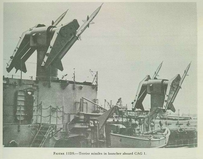
The twin launchers on CAG vessels (the present two are former CAs) are mounted above ammunition hoists which mechanically lift the missiles into the launcher. Reloading can be done twice a minute. It has been stated that two Terriers are normally sufficient to bring down any aircraft. Figure 11D9 shows Terriers in their launchers aboard CAG-1.
An Army-developed missile similar in mission to Terrier is Nike, which is used in defense of ground installations and cities. Nike is not fired from naval vessels.
Talos is a newer naval SAM larger than Terrier. At least one light cruiser is being modified to carry it.
Regulus is one of several SSMs developed for naval use. It is a high-subsonic-speed pilotless bomber which can be launched from any of several types of ship, including submarines. It can be fired from demountable launchers or from steam catapults. Another SSM still under development is the Loon.

Sparrow is a rocket-propelled AAM now operational in the Fleet. (See fig. 11D10.) It is guided by a radar beam transmitted from the launching aircraft. Sparrow is about 12 feet long, weighs around 300 pounds, and can attain a speed of 1,500 knots within a few seconds after launching. It has proved effective against both high- and low-altitude targets, even while they are taking evasive action.
Sidewinder is another rocket-propelled AAM. At this writing, details of this missile are classified.
Development is close to completion on the AUM Petrel. This is essentially a homing torpedo mounted in an airframe with its own jet engine. It flies for some distance after launching, jettisons its airframe and engine when it strikes the water, and then functions as a homing torpedo against a submerged or partly submerged target.
Aerobee is a research vehicle. It is a rocket capable of speeds up to 2,000 knots and altitudes of 78 miles. It carries instruments rather than a war head.