
Chapter 5 of NavPers 10797-A, Naval Ordnance and Gunnery, Volume 1 surveys the major structural and mechanical features that distinguish the modern naval gun mount from its predecessors. It covers the ten key developments — improved metallurgy, rifling, breech-loading, firing systems, recoil and counterrecoil, mechanical ammunition feed, power hoists, safety features, sighting, and power drives — and concludes with a summary of definitions and a list of guns then in U.S. Navy service.
A. Introduction
5A1. Development of guns
As the Foreword to this course indicates, guns have been used in warfare ashore and afloat for several hundred years. The Foreword indicates, in broad outline, how its effectiveness as a weapon has increased over this period of development. But this development has not been a slow, steady growth. For the first 400 years the technology of gunnery changed so little that, as the Foreword points out, one of Drake's men would have had to learn very little that was new to have served a gun at Trafalgar. Nearly all the basic features that have made the modern naval gun the effective weapon it is today have been developed within the past 130 years, and most of them began to become important only after the turn of the century.
Modern guns and mounts, with their associated sighting and fire control equipment, represent a highly developed technical level of achievement, not the less impressive because most of their features were initiated from 1 to 4 generations ago. Yet the guns and mounts aboard modern United States naval vessels, complex though they are in detail, are based on these relatively few fundamental features. Once they are grasped, the student will find it easier to master the details of structure and functioning of any gun mount or turret he encounters.
5A2. Scope of this chapter
This chapter is devoted principally to those significant features of modern naval guns that have been responsible for making of them the effective weapons they are today. Each of them is discussed individually in somewhat simplified form, with enough detail regarding its application to facilitate the student's understanding of operating principles when he encounters them in actual guns and mounts aboard ship. These features include:
- Improved metallurgy and barrel construction.
- Rifling.
- Breech-loading mechanisms.
- Percussion and electrical firing systems.
- Recoil and counterrecoil systems.
- Power rammers and mechanical ammunition feed.
- Power-driven ammunition hoists.
- Safety features — salvo latch, safety link, gas ejection.
- Sighting and fire control equipment.
- Power drives for elevating and training.
The next section of this chapter will take up first the common or conventional structural features of naval guns and mounts, then will discuss individually the characteristic structural and functional elements of modern naval gun mounts, as listed above.
The final section of this chapter presents, in summary form, fundamental definitions relating to guns and mounts.
B. Features of Modern Naval Guns and Mounts
5B1. Common structural features of naval gun mounts
Figure 5B1 is a closeup phantom view of a 5"/54 mount Mark 39. Though this particular mark is not the commonest of 5-inch mounts, it is a good example of the conventional type of mount that shows the features with which this chapter is particularly concerned. It differs structurally from most other 5-inch mounts principally in having a longer barrel. There are other differences in power drives and hoist arrangements with which we are not concerned at the moment.
Besides showing (as a phantom) the shield which protects the mount, figure 5B1 shows also a number of the major mount components which are essential to its proper functioning but are structurally accessories rather than basic parts. Such units pointed out in figure 5B1 include parts of the elevation controls and power drive (on the left side of this mount), the pointer's sight telescope, the mount captain's open sight (in the shield overhead), a ventilator duct (also in the shield), and parts of the hoists and fuze setter. On the other (right) side of the mount are the trainer's controls and power drive.

In figure 5B2 these accessory units are stripped away to reveal what might be considered the "skeleton" of the gun mount.
Serving as the mount foundation is the stand, a steel ring bolted to the deck. The training circle is an internal gear inside the stand. Supported by the stand, and capable of rotating in train in roller bearings on it, is the base ring. It may also be called the deep section ring or lower carriage. Mounted on it is the upper carriage, which is a pair of massive brackets braced to hold the trunnion bearings. The trunnion bearings are large roller bearings into which the gun trunnions fit. The trunnions are part of the slide, a rectangular weldment which supports all the elevating parts of the gun. The housing slides in recoil in the slide; the barrel fits into the housing's forward end, and the breechblock can slide up and down in a breechway just behind the barrel. Arrows show the movement of which each part named (except the breechblock) is capable.

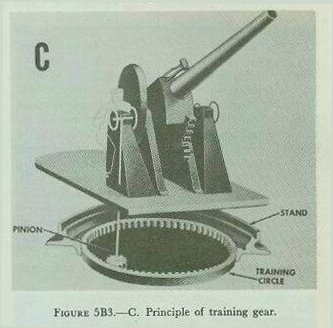
Now consider these parts in further detail. Figure 5B3 shows how the lower carriage or base ring fits into the stand, and how the mount can move in train. Angle brackets called holding-down clips bolted to the base ring fit under the stand so that the carriage will not tip off the stand when the gun is fired or when the ship pitches and rolls. The base ring can turn on the stand in two large-diameter roller bearings. One takes up vertical thrust; the other, horizontal. The function of the training circle is illustrated in figure 5B3; a pinion in the carriage engages the internal gear of the training circle to train the mount.
The carriage assembly is generally considered as two pieces — the lower carriage (base ring) and upper carriage — though on 20-mm mounts the distinction is unimportant. Figure 5B4 highlights these elements. The base ring supports the upper carriage, and the platform or working surface; the shield (in enclosed mounts) is secured to it. It also supports the mount power drives and other components. In mounts equipped with hoists, the hoists are suspended from the base ring and train with the mount. The upper carriage, which in 5-inch mounts may be called the carriage cheeks and in turrets is called the deck lug, is principally the support for the trunnion bearings (figure 5B4). The trunnion bearings and trunnions, in addition to serving as a support which permits the elevating parts to move in elevation, also provide a connection point for air lines (for gas ejection) and mechanical linkages (for mechanical firing linkages and for transmission of elevation movement to firing stop mechanisms).


The trunnions are a part of the slide (fig. 5B5), which is conventionally a rectangular steel weldment which houses or supports all the parts of the gun and mount that move in elevation. In modern mounts designed to engage either air or surface targets the limits of elevation movement are from minus 10 to 15 degrees (that is, with gun barrel depressed 10 to 15 degrees below the horizontal) to about plus 85 degrees. Because of the limitations imposed by turret structure, elevating mechanism, and ammunition feed equipment, turret guns of older design are not capable of these extremes of elevation.
Figure 5B5 points up the slide and the elements of elevating gear. The slide contains the ammunition feed mechanism (or the power rammer where ammunition feed is performed manually with mechanical assistance), the recoil brake, the counterrecoil mechanism, the elevating arc, and the gun housing. The arc is a gear sector secured to the slide. It engages a pinion in the carriage. The pinion may be driven manually or by an elevation power drive.


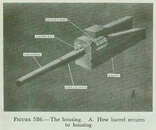
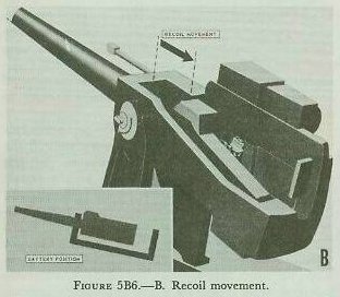
The recoiling parts (that is, those that move to the rear when the gun is fired) of a conventional naval gun are either attached to or are housed in the gun housing (also called the breech housing). The housing and related parts are highlighted in figure 5B6. Secured to the forward end of the housing is the gun barrel itself. The commonest method of attaching gun to housing is by use of a bayonet joint or interrupted-screw joint, with a key to lock the barrel against possible rotation. The housing can move parallel to the gun bore axis in ways in the slide. It is normally forced to its forward-most position (called battery position) by a counter-recoil mechanism, which may be either a powerful coil spring or a pneumatic device. When the gun fires, the reaction of the barrel forces the housing aft; this movement is opposed by the counterrecoil mechanism and by a hydraulic recoil brake. Figure 5B6 also indicates the location and some features of the breech mechanism. The type used in most guns of conventional design, including the 5-inch, and illustrated here, is called the vertical sliding-wedge type.


5B2. Gun barrel construction
Superficially, the modern gun barrel resembles very closely its ancestor of several hundred years ago. The old and the new both are thick-walled metal tubes. The propellant charge and projectile occupy the breech end when the gun is loaded, and the projectile, when fired, issues from the muzzle end. But with this the resemblance ends. Figure 5B7 shows in cross section the old look and the new in gun barrel profiles. The difference in shape is very significant.
1. At the breech end is a plug or breechblock which can be opened for loading the gun.
2. Just forward of the breech plug is an enlarged chamber to contain the propelling charge.
3. The bore is rifled — a set of spiral grooves twists the projectile as it moves toward the muzzle, so that it is spinning when it leaves the gun. In newer types of larger guns, the rifling is cut in a liner — a tubular insert that can be replaced when worn. In other guns, the rifling grooves are cut into the barrel.
4. As compared with early guns, the barrel walls are much thinner in modern guns, and the taper is much less exaggerated. Improved propellants and improved steels have together brought about this silhouette.
The thinnest part of the barrel, just aft of the bell, is the neck. Then comes the tapering chase, followed by the slide cylinder, which moves in a bearing in the slide during recoil. The after part of the barrel is secured to the gun housing.
Modern guns using pyro or triple-base propellants develop maximum gas pressure far more smoothly than early black-powder guns, and this is reflected in the silhouette of the modern barrel. The thinner barrel walls of modern guns are evidence not only of more effective propellants but also of improved metallurgy. Prestressing by shrinkage-fit hoops (built-up guns) or by the radial-expansion (autofrettage) process allows inner layers to be placed in initial compression, enabling the barrel to withstand far higher pressures than a simple hollow cylinder of the same weight.

5B3. Rifling
Early guns were smoothbore cannon capable of hurling a projectile to a respectable range, but their fire was so inaccurate that a gun capable of an extreme range of about 2,000 yards was considered reasonably certain to hit its target only at point-blank range — up to 80 or 100 yards. One reason was that smoothbores could fire only round shot, which, while dense, could not be made sufficiently elongated to take advantage of the theoretical maximum of kinetic energy. An elongated projectile needs spin to fly stably; a smoothbore cannot impart spin.
Rifling the old muzzle-loading cannon was impracticable because of the difficulty of ramming close-fitting ammunition down the length of the bore. Such ramming was possible in small arms (rifled shoulder weapons were used by infantry in the American Revolution) but not in cannon.

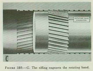
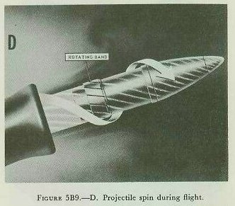
Figure 5B9-A illustrates how these problems are solved in modern conventional naval guns. First, the projectile is elongated with an ogival forward end. Breech-loading permits an enlarged chamber which contains more propellant of a slower burning and less erratic type than black powder. The projectile has a copper or alloy rotating band. The chamber is connected to the bore proper by a short tapering forcing cone. When the projectile is rammed into the gun, the rotating band forcibly engages the forcing cone. The gun bore is grooved or rifled with a helical spiral. The rifling begins at the forcing cone and continues to the muzzle. In all naval guns and small arms except the .45 caliber pistol, the rifling has a right-hand twist.


5B4. Breech mechanisms
Rifling could not be applied in a practical way to artillery until effective mechanisms were developed to permit loading from the breech end of the gun. With but one exception, all naval guns in present use in calibers 40-mm and larger use one of two general types of breech mechanism: the Welin interrupted-screw type (used in bag guns) or the vertical sliding-wedge type (used in 40-mm, 3-inch, 5-inch, and 6-inch guns, and in 8-inch turret guns for case ammunition).
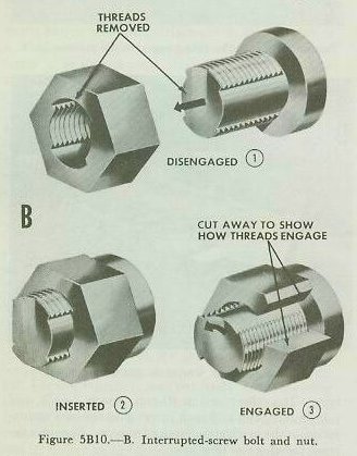
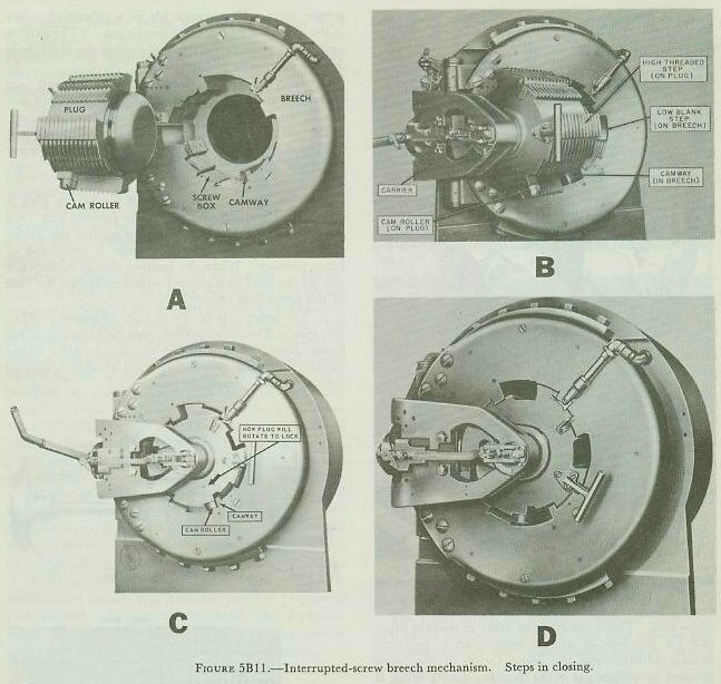
Interrupted-screw breech mechanism. The mass of a breech plug designed to withstand the 40,000 psi gas pressure of a typical large-caliber cannon is considerable — the breech plug of a 16-inch naval gun weighs about 1,400 pounds. Application of the interrupted-screw principle reduces the number of turns required to lock the plug to a fraction of a revolution. The Welin stepped-thread design takes this further: both plug and breech have steps arranged so that about 75 percent of the engaging surfaces are threaded, and only about 27.5 degrees of rotation is needed for full engagement.


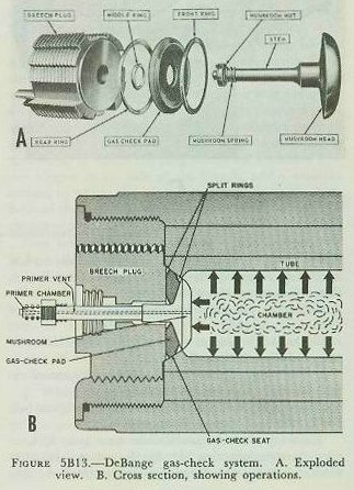
The interrupted-screw plug requires an obturator or sealing device — the DeBange gas-check system — to prevent leakage of burning powder gas into the turret or mount. Its main parts are the mushroom, gas check pad, split rings, and gas check seat. The mushroom is forced hard back against the gas-check pad by the propellant gas pressure, causing the pad to expand against the gas-check seat and form an effective seal. The greater the gas pressure, the harder the mushroom compresses the pad.

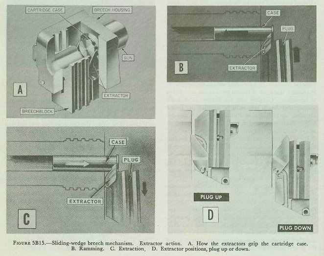
Vertical sliding-wedge breech mechanism. Guns 40-mm and up, of late designs, use a breech mechanism that works on a completely different principle — the sliding-wedge breech mechanism. This uses a sliding element to block off the breech opening. In its raised (closed) position the breechblock moves forward as well as upward, wedging the cartridge case into the gun chamber. Obturation depends entirely on the cartridge case for sealing effect: as the propelling charge burns, the hot powder gases expand against the sides of the cartridge, which in turn expand against the smooth walls of the chamber and against the breechblock. All guns with sliding-wedge breechblocks have one or a pair of extractors as part of the breech mechanism, operated by breechblock movement.

5B5. Percussion and electrical firing systems
The firing mechanism (also called the firing lock) is secured in the breechblock and is very easily removed for cleaning. The illustration shows a combination electric-percussion firing mechanism typical of case guns 3-inch and larger. Mechanical linkage in the breechblock retracts the firing pin when the breechblock is not fully closed, and cocks and releases the firing pin to fire the cartridge case by percussion or electric means.

In electric firing, all that is necessary is for the firing pin or striker to maintain good electrical contact with the case primer. When the firing circuit is closed, current passes through the cable and the firing pin through the primer's contact and filament, then by way of the cartridge case and gun to ground. The breech mechanism device which retracts the firing pin automatically prevents firing both by percussion and electrically when the breech is not fully closed.
Figure 5B17 shows in simplified form the firing linkage for a conventional 5"/38 mount. The treadle tilts down, swinging the rectangular connection lever assembly aft, and so rotating the firing rod. A firing rod lever at the top of the firing rod pushes the outer push rod, which runs inboard through the inner surface of the slide. The trip plate transmits the push to the inner push rod in the housing. If the breechblock is fully closed, the inner push rod accomplishes the entire purpose of this linkage: to push the sear to the right. Two important safety features: (1) the trip plate can push the inner push rod only when the gun is completely in battery; (2) the inner push rod can push the sear only when the breechblock is fully closed.

In bag guns the primer is in a small cylindrical case loaded separately into a primer chamber. The firing lock in general performs the same function as the firing mechanism in a sliding-wedge breechblock. All bag guns now in active use in the Fleet use the same firing lock, the Mark 14. It has a little sliding-wedge type breech mechanism mechanically linked to the gun's breech plug so that it normally closes and opens with the plug. For electric firing, the firing lock has a terminal to which a lead from the electrical firing circuit can be attached. For percussion firing a lanyard is connected to the cocking lever on the lock.


The firing stop mechanism disables the firing system when the gun is aimed on a bearing or elevation that endangers the ship on which it is mounted. It is essentially a disc-type cam, in which the inputs are gun train (which rotates the cam) and gun elevation (which moves the cam follower approximately radially across the cam). When the gun mount is installed, the axis of its bore is observed through all angles of train and elevation. Safe areas are machined away (depressed); danger areas remain the original surface of the plate. When the plunger rides on a high (danger) cam plate area, the clutch is disengaged, interrupting percussion fire, and the switch is opened, interrupting electrical fire. Firing stop mechanism functioning is completely automatic.

5B6. Recoil and counterrecoil systems
Modern guns have recoil and counterrecoil mechanisms; ancient guns did not. A naval gun can be rigidly secured to the deck, but without some provision for its recoil it will break loose when fired. Recoil is simply the manifestation of Newton's third law of motion — to every action there must be an equal and opposite reaction. A recoil brake is primarily designed to absorb the force of recoil and spread it so that the sudden heavy shock is converted to a thrust exerted over an appreciable distance through which the recoiling parts are permitted to move. A counterrecoil mechanism stores some of the energy of recoil and uses it to force the recoiling parts forward into battery after the projectile has left the gun muzzle.

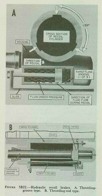
All present-day recoil systems for naval guns larger than 20-mm use hydraulic recoil brakes. A hydraulic recoil brake is a dashpot mechanism with a piston and a cylinder, with a liquid that can move from one side of the piston to the other at a throttled rate. Two general variants are used: (A) a solid piston in each cylinder with three throttling grooves cut in the cylinder wall, which are shallow at the forward end and deepen toward the after end; and (B) a piston with three holes through which tapered throttling rods pass, used in 6-inch and larger guns. In the conventional 5-inch gun there are two recoil cylinders, symmetrically arranged about the long axis of the housing.
There are two basic types of counterrecoil systems. Guns smaller than 5-inch use one or more counterrecoil springs. Guns 5-inch and larger use pneumatic recuperators — hydropneumatic counterrecoil systems — in which compressed gas (generally air or nitrogen) sealed by oil-inflated chevron packing provides counterrecoil thrust. The differential cylinder ensures that oil pressure in the packing is always higher than gas pressure in the cylinder, regardless of fluctuations in gas pressure.


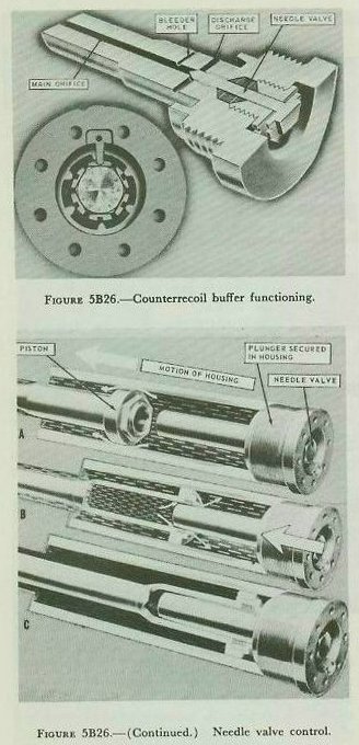
Counterrecoil buffers are dashpot devices which use oil forced through small orifices to reduce the velocity of counterrecoiling parts at the end of the counterrecoil stroke. In conventional 5-inch gun designs, the buffer plunger enters a hole in the recoil piston as counterrecoil movement nears battery position, trapping fluid that can escape only through small passages controlled by a needle valve.
5B7. Power rammers and mechanical ammunition feed
The effectiveness of a gun as a weapon depends on the number of rounds per minute it can put into the target. Mechanical loading and feeding devices are important in achieving high rates of fire. In 5-inch mounts through Mark 39, separate power rammers are used for moving into the gun chamber ammunition which has been loaded into the slide. Figure 5B27 shows a slide-mounted rammer on a 5-inch mount: a piston in a long hydraulic cylinder operates a reciprocating rubber-faced rammer spade. When the gun fires, the rammer spade rides backward with the housing, automatically initiating the rammer retract stroke.

Bag-type turret guns have long chambers requiring a very long rammer stroke, for which chain-type rammers are used. A rotary hydraulic motor drives a sprocket engaging a rammer chain that will remain straight without continuous support when extended horizontally. The ramming operation requires two strokes: the first rams the projectile home at full thrust to ensure the rotating band engages the rifling; the second, lighter stroke rams the powder bags.

5B8. Power-driven ammunition hoists
Figure 5B29 shows in cutaway form the ammunition supply arrangements for a modern 5-inch twin mount. At the lowest level is the magazine containing propelling charges. Powder cases are passed by hand through scuttles in the magazine bulkhead to the lower handling room, then loaded into dredger hoists hauling them to the upper handling room. From there, separate projectile hoists and powder hoists carry them to the gun deck level.

All gun ammunition hoists on modern United States naval vessels fall into four categories: (1) endless-chain (hoist-or-lower multistage, and hoist-only single-stage); (2) elevator; (3) pawl; and (4) open-tube. The most widely used is the first class. Important safety features include automatic start interlock requiring the ammunition item to be fully inserted before starting, interlock preventing start if the top level is occupied, flametight doors on all powder-bag hoists, provisions for manual operation on power failure, hydraulic brakes preventing loaded cars from drifting down the hoistway, and indicators showing whether ammunition is at the receiving end.


5B9. Miscellaneous safety features
Salvo latch. This is a device that locks the breech closed. It can be opened only by deliberate effort. The function of the salvo latch is to prevent accidental manual opening of the breech in the event of misfire. The salvo latch is a positive lock which is cammed to open automatically during recoil of the gun. It will not open automatically if the gun does not recoil.
Safety link. The safety link is a metal strip that couples the breech yoke (in bag guns) or housing (in case guns) to the slide. It is intended to hold the gun in battery in the event of failure of the counterrecoil mechanism. If the gun is fired with the safety link engaged, the link will part. It is part of the normal gun operating procedure to disconnect and stow the link before firing.
Gas ejection. When a shot is fired from a gun, the bore is filled with residual powder gas that is unsafe for humans to breathe and is sometimes capable of spontaneous combustion when mixed with air. The gas ejector is a part of every enclosed mount 5-inch and larger. In case guns it opens and shuts off automatically during normal operation; in bag guns it goes on automatically when the breech plug opens but must be shut off manually by the gun captain.
5B10. Sighting and fire control equipment
With the increase in ranges of modern guns, aiming has become more complex. The fire control system computes the angle by which the bore axis of the gun should be offset from the straight line between the gun and the target — the line of sight (LOS). The offset is divided into two components: sight angle (vertical) and sight deflection (horizontal).
The sights at the gun provide for establishing the line of sight and for introducing sight angle and sight deflection. In gun mounts 3-inch and larger, sights generally consist of telescopes that move with the gun and can also be moved vertically and horizontally with respect to the bore axis to introduce the sight corrections. The pointer, trainer, and sight setter work as a three-man team: the pointer keeps the horizontal crosshair on target and elevates the gun to introduce sight angle; the trainer keeps the vertical crosshair on target and trains the mount to introduce sight deflection.

5B11. Types of sights
The simplest type of sight now in use is an open sight consisting of a small peephole behind a vertical rod. An almost equally simple type is the peep-and-ring sight; an example is visible in figure 9C1 installed on a 40-mm mount. The rear part is a peephole; the front part consists of concentric rings used not only to establish the line of sight but also to estimate lead angle for fast-moving air targets. These open sights are used only for local control in emergencies or for slewing a gun mount toward the approximate location of a target.
Telescopic sights permit more accurate sighting. There are two general types: the fixed-prism (in which the entire telescope is moved to offset the line of sight) and the movable-prism (in which internal prisms can be shifted to offset the line of sight). A third general type, the lead-computing sight, has movable optical parts and computing mechanisms which automatically offset the line of sight.


5B12. Train and elevation systems
One important respect in which today's naval gun differs from its ancestors is in the improvement in (a) the methods available for positioning it in train and elevation, and (b) the methods available for measuring or shifting it to a prescribed position.
In a modern gun mount, the trunnions are placed where the gun is approximately in balance. The pointer's handwheels turn a pinion which rotates a gear sector on the slide called the elevating arc. The trainer's handwheel, through gearing, turns a gear that engages the training circle in the stand. In bag-type turrets, where maximum elevation is limited and the mass of the parts to be elevated is especially great, the elevating gear turns an elevating nut which engages a screw pivoted to the gun slide. Turrets of the case type use an arc-and-pinion type of elevating gear.
All turrets, and mounts larger than 20-mm, use power drives as the normal method of positioning, though the pointer and trainer can readily switch to manual operation.

C. Conclusion
5C1. General
The preceding section provided an overview of the 10 major features or characteristics which distinguish the modern gun from its predecessors. Not all of these features will be found in all modern guns — particularly in small arms and machine guns. And there are considerable variations in details of design from one mark and mod of weapon to another. But the features described are those referred to elsewhere in this book as "conventional," meaning that they represent standard practice in the art of gun and mount design as it exists in the United States Navy about the middle of the 20th century.
5C2. Review of definitions
Following is a brief list of definitions which summarize in general form some key terms used in the preceding section.
Gun. The term gun properly designates the tube or barrel, but is commonly used to refer to the whole assembly of which the barrel is but a part.
Mount. This is the entire system between the gun and the ship's structure which supports the gun, secures it to the ship's structure, and provides for its elevation, train, and (in guns larger than 20-mm) recoil and counterrecoil.
Train. The train of a gun is the position of the axis of the gun's bore in azimuth, as measured from the ship's centerline. Training the gun is rotating it in azimuth.
Elevation. The elevation of a gun is the angle that the gun bore axis makes with the deck, measured perpendicular to the deck. Pointing the gun is increasing (elevating) or decreasing (depressing) this angle.
Recoil. Recoil is the force tending to push the gun to the rear as the projectile is discharged. The recoil mechanism is the equipment used to control the gun recoil.
Counterrecoil. Counterrecoil is the forward movement of the gun after recoil which returns the gun to its original firing position. The counterrecoil mechanism (also known as the recuperator) is the equipment that returns the gun to its firing position.
In battery. A gun in its firing position as regards recoil and counterrecoil is said to be in battery.
Housing. The housing of a gun is a generally box-shaped structure joined to the gun barrel with a bayonet-type joint. It houses the breech mechanism in most intermediate-caliber guns. Since it is attached to the gun barrel, it is a recoiling part.
Slide. On all guns larger than 20-mm, the slide is the structural part which supports the gun, housing, and other recoiling parts, and permits them to move in recoil.
Automatic guns are case guns in which some of the energy of the propellant explosion is used to open the breech, eject the empty case, and operate the device which automatically loads another round of ammunition.
Semiautomatic guns are case guns in which some of the energy of the propellant explosion is used to open the breech, eject the empty case, and automatically close the breech when another round is loaded; loading itself is not automatic.
Nonautomatic guns are those in which none of the energy of the propellant is used to perform breech opening, closing, or loading functions. All bag guns are of this type.
Rapid-fire (RF) guns are those in which loading, firing, empty-case ejection, and breech operation are performed automatically but are powered by a source of energy other than the propelling charge.
5C3. Designation of guns by caliber
The caliber of a gun (the diameter of its bore measured to the tops of the lands) is expressed in inches or millimeters. For all guns of caliber 3-inch and above, the length of the gun barrel is customarily expressed by dividing the length of the bore plus the length of the chamber by the diameter of the bore. Thus a 3"/50 caliber gun barrel has a caliber of 3 inches and is 50 calibers or 150 inches long.
Guns are classified according to bore diameter:
- Major-caliber — 8 inches or larger.
- Intermediate-caliber — greater than 4 and less than 8 inches.
- Minor-caliber — greater than 0.60 inch but not more than 4 inches.
- Small arms — 0.60 inch or smaller.
5C4. Guns in service
Guns most likely to be found on Navy ships at the time this text was written:
| Gun | Carried on |
| 16"/50 caliber | Battleships |
| 16"/45 caliber | Battleships |
| 12"/50 caliber | Large Cruisers |
| 8"/55 caliber | Heavy Cruisers |
| 6"/47 caliber | Light Cruisers |
| 5"/54 caliber | Large carriers, destroyers, and frigates |
| 5"/38 caliber | Battleships, cruisers, destroyers, carriers, and auxiliaries |
| 5"/25 caliber | Submarines |
| 3"/50 caliber | Any ship from patrol craft to battleship |
| 40-mm | Any ship from patrol craft to battleship |
| 20-mm | Any ship from patrol craft to battleship |