Chapter 7 of Naval Ordnance and Gunnery, Volume 1 (NavPers 10797-A, 1957) covers the design and operation of U.S. Navy gun turrets from the massive 16"/50 three-gun turrets of the Iowa class battleships through the rapid-fire 6"/47 and 8"/55 case-gun turrets of Worcester and Salem class cruisers. The text was prepared by the Department of Ordnance and Gunnery, United States Naval Academy, as the standard midshipmen's reference on turret construction, elevating and training gear, ammunition handling, and firing operations.
A. Introduction
7A1. General
The type of gun emplacement called a turret is, in general, that in which several heavy guns of at least 6-inch caliber are mounted in an armored structure which is revolved on rollers by suitable machinery, the guns being elevated independently of the structure.
The Bureau of Ordnance designates ordnance equipment as gun mounts or as gun turrets according to the division of cognizance between that bureau and the Bureau of Ships. In general, if the equipment is massive enough to require assembly of parts on the ship as it is being built, it is called a turret. If the assembly is made in a gun shop and then hoisted aboard as a complete unit, it is called a gun mount.
Turret installations on present United States Navy ships are equipped with guns of 6-inch caliber or larger. All turrets have either 2 or 3 guns. They are the primary offensive armament or main battery of cruisers and battleships.
7A2. Turret arrangement
Turrets are located fore and aft on the centerline of the ship, so that they are able to fire on either beam. Some turrets are built higher than the adjacent ones, so that they can shoot over them. This arrangement provides the maximum arc of fire, usually about 300 degrees per turret.
7A3. Turret armor
All turret structures are protected by armor plate. The gun house is protected by heavy armor plate on the face, sides, roof, and rear. Surrounding the rotating structure below the gun house and extending to the armored decks of the ship, is a fixed cylinder of heavy armor called the barbette. The lower spaces of the turrets are protected by the side armor belt of the ship, and by the armored decks of the ship. All the turret structures, therefore, including the powder stowage magazines, are completely surrounded by heavy armor protection.
7A4. Description of a typical bag-gun turret
All turrets equipped with bag guns are essentially similar. The major portion of this chapter is devoted to a detailed description of the 16"/50 caliber 3-gun turret as installed on the Iowa class battleships.
Other modern major-caliber turrets such as the 16"/45 caliber, 12"/50 caliber, and 8"/55 caliber (Baltimore class) differ from the turret described in many mechanical details, but in general the installations and equipment perform the same basic functions. Therefore, if the operation of one of these assemblies is thoroughly understood it is a relatively simple matter to learn the details of the others from appropriate ordnance publications.
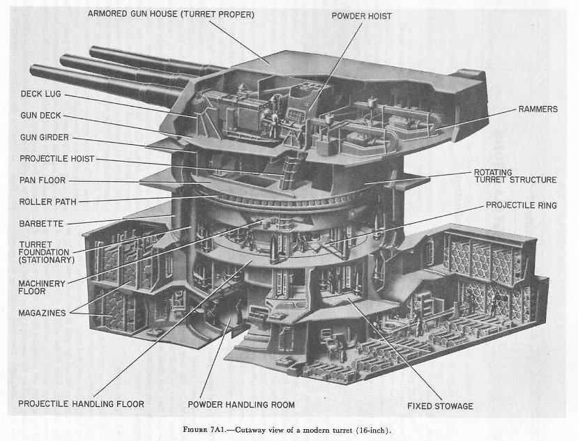
The 16"/50 caliber turret has its equipment located on six separate levels. These are (1) the gun house, (2) the pan floor, (3) the machinery floor, (4) and (5) the upper and lower projectile flats and (6) the powder-handling room. See figure 7A1.
The first (upper) level, or gun house, contains the turret officer's control booth, the gun compartments, and the right and left sight stations. See figure 7A2. All of these compartments are separated by flametight bulkheads. The after part of the gun house contains the only entrance hatch to the turret from the weather deck. The hatch opens into the turret officer's booth. Located in the booth are the range-finder, the local control computer, the fire control and communications circuits necessary for turret control, and the power equipment for the rammer mechanisms. The three separate gun compartments, or gun rooms as they are commonly called, have the controls and equipment necessary for servicing the guns. The two sight stations contain duplicate equipment for the operation of the turret optical sights by the pointers, trainers, and sight setters.
The second level, counting downward, is called the pan floor. It contains the pockets or open pits into which the breeches of the guns are depressed as the guns are elevated. It also contains operating machinery as shown in figure 7A3.
The third level (downward) is the machinery floor on which are located the stations for the three gun layers and the turret trainer. They operate the machinery which moves the guns in elevation and the turret in train in response to fire control orders. This level is a maze of electric-hydraulic machinery necessary for turret operation. See figure 7A4.
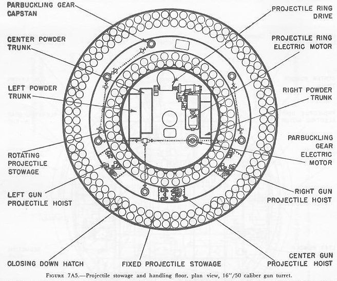
The next two levels down are the upper and lower projectile stowage and handling rooms, shown in figure 7A5. Here the projectiles are taken from the stowages, loaded into hoists, and lifted up into the gun rooms.
The lowest level is the powder-handling room. Surrounding the handling room are the fixed powder stowage magazines. The bags of powder are passed from the magazines through flameproof openings called powder scuttles into the handling room. Here the bags are loaded into elevator-type hoists which deliver them to the gun rooms.


B. Gun and Breech Assembly
7B1. The gun
The 16"/50 caliber gun is a built-up gun consisting of a liner, a tube, a jacket, three hoops, and a yoke ring. It has an overall length of 68 feet, and a maximum outside diameter of 46 inches at the slide cylinder. The total weight is approximately 120 tons. The rifling has a uniform twist of 1 turn in 25 calibers. The bore is chromium plated to retard erosion. The powder chamber is slightly less than 18.5 inches in diameter and about 9 feet long.
The screw-box liner is screwed into the breech, and its inner surface provides the stepped threads which engage those on the Welin-type plug. Ducts between the gun and the liner, and holes through the latter, provide the air leads of the gas-ejector system.
The yoke is mounted around the breech end of the gun to provide the means for securing the recoil piston rod and the two counterrecoil cylinder yoke rods to the gun. See figures 7C1 and 7C2. The yoke also helps to counterbalance the gun. The yoke is secured to the gun by a key, a fixed ring, and a locking ring. A shoulder on the yoke butts against the rear face or breech end of the fixed ring secured to the gun in an annular groove. The locking ring screws into the yoke and holds it in place against the fixed ring. The key prevents rotation about the gun axis.


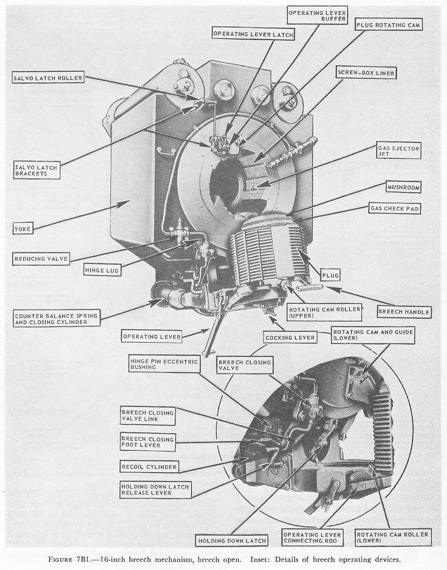
7B2. Breech mechanism
The breech mechanism is shown in figures 7B1 and 7B2. Its principal parts include: (1) a Welin-type plug, (2) a mushroom and gas-check pad, (3) a carrier, (4) counterbalance springs and closing cylinder, (5) rotating cams, (6) an operating lever and connecting rod, and (7) a salvo latch.
Welin plug and gas seal. The plug rotates 29° to lock to the screw-box liner. The design of the blank sectors permits the two plug-rotating cams to rotate the plug slightly over 6 degrees before the threads engage while the breech is closing. The cam action assists in obtaining a smooth transition between plug translation and rotation.
The mushroom and gas-check pad are the conventional De Bange type described in article 5B4. An indication of the mushroom size is that its weight is over 220 pounds.
The plug is mounted on the carrier as shown in figure 7B3. The threads on the carrier journal and in the plug recess have a pitch of 0.9 inch. This means that the plug will move aft 0.9 inch per counterclockwise revolution. Since the plug is unlocked by a rotation of 29 degrees, it is evident that it will move aft on the carrier journal about 0.1 inch when the breech is opened. If the gas-check pad is stuck to the seating surface, the plug will pull away from the back of the pad and the compressed spring around the mushroom stem will tend to force the mushroom nut, and hence the pad, aft. This force ordinarily breaks the seal; but if it does not, the continued rearward movement of the plug separates the pad from its seat.
Carrier and associated equipment. The plug and carrier, which have a combined weight about 2,000 pounds, swing about a pivot supported by the hinge lug secured to the gun. The plug is locked in the open position by a holding-down latch until it is released by a foot crank near the loading platform.
The opening buffer functions to bring the downward movement of the carrier to a stop without shock. In construction and operation it is similar to a grooved-wall type of recoil brake. The counterbalance and closing cylinders are a combination of spring and pneumatic mechanisms which function to balance and check the weight of the breech assembly in opening and to furnish assistance in closing the breech. The cylinders receive their air supply from the gas-ejector system after the pressure has been reduced from 200 to about 40 psi. The counterbalance springs are so adjusted that the breech mechanism will swing down and latch without a jarring stop or rebound. The air pressure in the cylinders is set so that, when the air valve is opened by the gun captain, the breech will close and swing the operating lever nearly home. The swing of the lever is always completed by hand.
Operating lever and salvo latch. The operating lever is pivoted on the carrier and is connected to the plug by means of the connecting rod which extends from a pivot on the lever to a pin on the breech-plug rear face. Motion of the operating lever about its fulcrum as it is pulled aft causes the connecting rod to rotate the plug and unlock it from the screw-box liner. A beveled, spring-loaded plunger in the end of the lever engages the operating-lever latch when the breech is fully closed. (See fig. 7B2.) The swing of the operating lever is stopped by the operating-lever buffer, which is similar to the opening buffer.


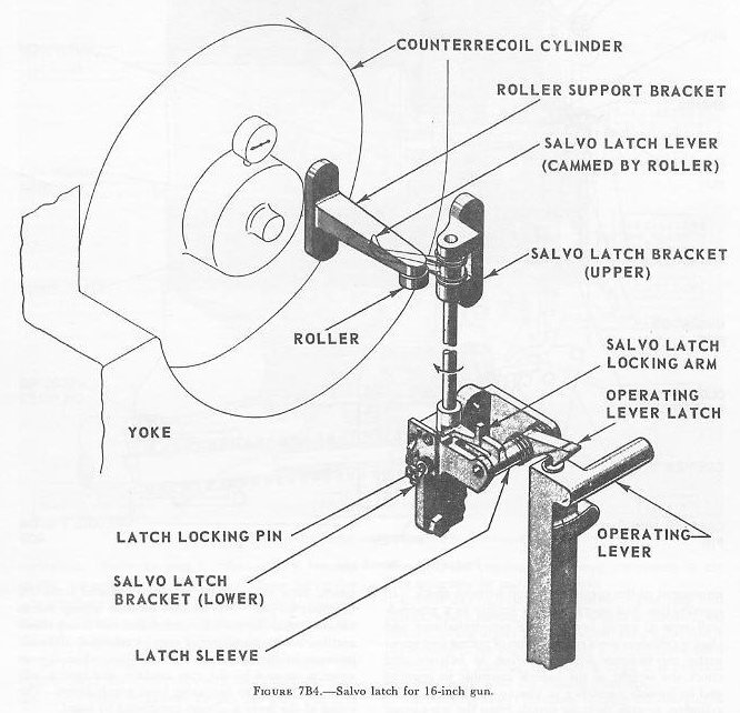
The salvo latch is an automatic latching device of the positive action type. It functions to prevent lifting of the operating-lever latch when the breech is closed until after the gun has fired. It releases the lever latch as the gun recoils, so that it may be lifted subsequently. Figure 7B4 shows the assembled arrangement.
The roller support bracket and roller are mounted on the counterrecoil cylinder. They are the only parts of the salvo latch assembly which do not recoil. As the gun recoils, the salvo-latch lever moves past the roller, and is rotated by it. This turns the shaft and the salvo-latch locking arm. The locking arm is caught and held in its displaced position by a latch catch (not shown in the figure). This action also holds the salvo-latch lever in its displaced position. The locking arm is thus held out of the way of the lug on the latch sleeve. The operating-lever latch, being integral with the latch sleeve, can now be raised against spring pressure to release the breech-operating lever.
After the gun has returned to battery, the plugman opens the breech. His action of raising the operating lever latch rotates the sleeve and depresses the latch catch, so that the locking arm springs back to its locking position. Then, when the breech is closed, the operating lever slides under the operating-lever latch, where it is caught and held.
For drills the salvo latch is secured in its unlocked position, so that the habit of manually unlocking the salvo latch will not be formed. This is accomplished by screwing the latch locking pin in hole B. The pin holds the salvo-latch locking arm in its displaced position. At all other times, it must be kept in the turret officer's booth.
7B3. Firing mechanism
The firing mechanism consists of a Mark 14 Mod 5 firing lock and the associated operating devices which synchronize its action with that of the operating lever. The firing lock, shown in figure 7B5, consists of a receiver which is attached to the end of the mushroom stem and a wedge which slides back and forth in the receiver, to open and close the primer chamber in the mushroom stem. The primer-retaining catch helps to hold the primer in place until the wedge closes; the extractor ejects the primer case as the wedge opens. The wedge contains an insulated firing pin which carries the current to the primer bridge for electrical firing. For percussion firing, a hammer, a contact piece, and a cocking lever attached to the wedge function to deliver a blow to the firing pin.
Safety features incorporated in the lock prevent firing until the gun breech and the firing lock are completely closed. These include:
1. A lug on the hammer slides in a groove in the receiver and lifts the hammer enough to break electrical contact between the firing pin and primer until the wedge is in the closed position.
2. The same lug also prevents the hammer from being drawn back for percussion firing until the wedge is in the closed position.
3. The hammer thrust pin must line up with a hole in the carrier before the cocking lever can be pulled back for percussion firing. This alignment occurs only when the wedge is fully closed.
4. The cocking lever is so constructed that it transmits any accidental blow directly to the wedge instead of to the hammer and firing pin.
The wedge is connected with the breech-plug operating lever by means of a lock-operating bar (fig. 7B2) and a mechanical linkage. The motion is such that the wedge is withdrawn and the primer extracted when the operating lever is pulled aft and down in opening the breech. To reprime in case of a misfire the wedge can be retracted, without opening the breech, by unlatching the retracting lever latch (fig. 7B2) and rotating the retracting lever. But the wedge cannot be fully closed unless the breech is closed and locked.

7B4. Gas-ejector system
The system includes a series of storage tanks, piping with the necessary swivel and expansion joints, the gas-ejector valve (fig. 7B2), the gas-ejector trip plate, passages through the screw-box liner, and nozzles which direct the air into the bore. Air at 150 to 200 psi from the ship's compressors is brought into the turret through the central column for the main gas ejectors, the auxiliary gas ejectors, and the pneumatic breech-closing cylinders.
From the tank the air is piped to the slide and thence through an expansion joint to the breech. The gas-ejector valve controls the flow of air in the ejector system. It is automatically opened by the gas ejector trip plate when the plug is turned for opening the breech, and is closed manually when the bore is clear. When the valve is opened, air is admitted to an annular space between the screw-box liner and the gun. Three equally spaced holes extend through the liner from this space, and nozzles are recessed into their ends. The air jets direct their streams forward toward the bore center.
An auxiliary ejector consisting of a hose with a quick-acting valve and nozzle is stowed overhead near the breech. This is a standby device which can be directed into the gun to clear the bore in case normal gas ejection by the primary means fails.
C. Slide Assembly
7C1. General
Although in general the principles of gun mount construction as discussed in chapter 5 apply to the gun slide, and deck lug structures of bag-type turret guns, there are important differences in some details, particularly with respect to the relationship of recoiling and nonrecoiling parts, and the locations of components of the recoil and counterrecoil systems. Therefore, in addition to figure 7C2, which shows in an exterior view the gun and slide of a 16-inch turret gun, figure 7C1 shows, in simplified exploded schematic form, the relationship of recoiling and nonrecoiling parts, and the locations of important parts of the recoil and counterrecoil systems. (Both figures are shown above in section B.)
Each gun has a separate slide which is individually mounted in trunnion bearings and is arranged for independent elevating movement. The main element is a steel forging with attached parts which include: (1) the trunnions, (2) the rear end brackets, (3) the loaders' platform bracket, (4) the hydraulic recoil system, (5) the counterrecoil recuperator system, (6) the slide-securing device, (7) the yoke-locking device, (8) upper and lower shield plates, and (9) a cylindrical gun cover. The complete assembly is over 33.5 feet long, 79 inches across the trunnions and 116.5 inches high. The total weight is 51.5 tons. All 3 guns in the turret are identical, except that a few components, found on one side of the right and center guns, are on the opposite side of the left gun. Figure 7C2 shows a left gun.
The gun-slide bore of the steel forging is fitted with 6 bronze liners, each 10 inches wide. The liners are provided with oil grooves and are the bearing surfaces on which the gun slides during recoil and counterrecoil.
7C3. The trunnions
Integral with the slide are the 18.5-inch diameter trunnion journals. Each of these journals rests in a specially designed roller-bearing assembly fitted into a deck lug (fig. 7A1) which is supported by the gun girder. Each bearing includes 24 cylinder rollers 2.5 inches in diameter and 3.5 inches long. These bearings carry the weight of the entire gun and take the shock of firing.
7C4. The rear end brackets
These brackets are bolted to the left and right side of the slide. One rear end bracket, as shown in figure 7C2, provides mounting attachments for the loaders' platform bracket and the slide-securing pin is seated in an aligned socket in an adjacent gun girder when the gun is at zero degrees elevation. The pin is forced into the socket by means of a handwheel-operated screw. This arrangement serves to relieve the elevating screw and drive gear from the effects of roll, pitch, and vibration when the gun is not being used. Another socket permits locking the gun at 20 degrees elevation while the recuperator air cylinders are being charged.
The other rear bracket on the slide mounts the large pivot pin to which the elevating screw is attached. (See article 7D1.)
7C5. Recoil mechanism
The recoil mechanism is the conventional hydraulic type and has a single cylinder of 26-inch bore diameter and an overall length of about 5 feet. It is similar to the one shown in chapter 5. Three equally spaced throttling rods control recoil fluid flow. The recoil is limited to 48 inches (3 calibers), occurring in approximately one-third second.
Counterrecoil buffing action is provided by a plunger-dashpot arrangement at the forward end of the cylinder. Liquid displacement from the dashpot occurs through four grooves of variable depth and through the small clearance between the plunger and the dashpot entrance. Buffing action takes place during the last 16 inches of counterrecoil. Two expansion tanks are mounted forward of the recoil cylinders.
7C6. Recuperator
The hydropneumatic counterrecoil mechanism consists of two air cylinders mounted on top of the slide and a differential cylinder between them. Its operating principles are discussed in chapter 5. The counterrecoil cylinders, shown in figure 7C2, are about 11 feet long and have an inside diameter of 11 inches. The plungers are hollow cylinders closed at the forward end, and are about 6 feet long and 11 inches in outside diameter. They are connected to the gun yoke by means of a plunger yoke and two yoke rods which are covered by the plunger cover.
7C7. Yoke-locking device
This device, which holds the gun in battery when it is not in use, even though pressure in the recuperator is lost, is on top of the slide, at the rear, between the counterrecoil cylinders. A safety link, in the form of an eyebolt, is pinned to the slide. When locked, the safety link rests in a notched bracket on top of the yoke, and a nut on the link is tight against the bracket, holding the yoke and gun securely to the slide. The link is stowed by loosening the nut, swinging the pin up and forward, and clamping it out of the way. If the link is inadvertently left in place when the gun is fired, it will part without damage to the gun, but it must be replaced without delay.
7C8. The shield plates and gun cover
The upper and lower shield plates are located just inside the gun port at the face plate of the turret. They form a weather and splinter shield for the slide. The gun cover is a 1/2-inch thick cylinder whose inside diameter is slightly larger than the gun's slide cylinder. It extends through the gun port about seven feet. At its forward end there is a wiping-ring assembly which serves as an oil and weather seal for the gun. A neoprene cover (gun buckler) clamps on the outer end of the gun cover and is attached on the sloping front face of the armor plate, completely enclosing the gun port.
D. Elevating, Training, and Sight Gear
7D1. Elevating gear
The three elevating-gear installations of each turret are independent assemblies. Each assembly consists of an electric-hydraulic power drive, an oscillating bearing assembly, and control mechanisms, shown schematically in figure 7D1. The greater part of these assemblies are located below the respective guns, forward and below the gun pockets in the pan and machinery floor spaces. The arrangements on these levels are shown in figures 7A3 and 7A4.

The electric-hydraulic power drive has a 60-horsepower electric motor driving a variable-displacement hydraulic pump (A-end) which supplies oil pressure to a fixed-displacement hydraulic motor (B-end), as described more completely in chapter 10. The B-end output shaft is connected to the elevating-nut drive. The elevating nut is threaded around the elevating screw and is mounted in the oscillating bearing, which allows the complete assembly to tilt. The elevating screw is secured to the pivot pin on the rear end bracket of the gun slide, and is moved up or down as the elevating nut rotates.
Gun-elevating movement is controlled automatically by means of a receiver-regulator or by rotation of the gun layer's handwheels on the machinery floor. In the latter method the gun-laying personnel (one gun layer for each gun) control the power drive in accordance with dial-indicated gun-elevation orders emanating from either the director system or one of the two sighting stations within the turret. Elevation stops are installed to limit elevation and depression to 45 degrees and minus 2 degrees respectively. The maximum elevating speed is approximately 12 degrees of arc per second. After firing the gun is automatically lowered to the loading angle of five degrees elevation by operation of a control lever.

7D2. Training gear
The training gear and its control equipment shown schematically in figure 7D2 also consists of an electric-hydraulic power drive which can be automatically or manually controlled. The electric motor (300 hp, with an overload rating of 540 hp) drives the A-end of the hydraulic transmission unit through a reduction gear. Two B-end units are driven by the single A-end.
The B-ends drive the training pinions, which mesh with the training circle secured to the turret foundation. The brakes between the B-ends and the pinions function to prevent the turret from turning when the training power is off. The brakes are set by springs and released by hydraulic cylinders. When power is off, no pressure is in the hydraulic cylinders, and the springs set the brakes. During training, a piston in each cylinder is forced upward by oil under pressure, releasing the brakes.
Training may be automatically controlled from the director system through a receiver-regulator, or locally controlled from either the gun deck or the machinery floor by handwheels. In indicator gun laying, either the train operator on the machinery floor trains the turret in accordance with dial-indicated train-order signals, received from the director system or turret sighting stations, or one of the sight trainers controls the drive by keeping his telescope on the target.
7D3. Sighting gear
Each 16-inch turret has duplicate sight stations in enclosed compartments located outboard from the wing guns and approximately on the transverse center-line of the turret. Each station transmits gun elevation or gun train orders to the indicators and control gear on the machinery floor from which the power is actually applied to the turret and guns. The pointer's and the trainer's telescopes are so mounted that they have parallel motions when the sight settings are made.
Corresponding elements of the two stations are interconnected so that either station can take over sighting operations. When this is done, the guns are indirectly positioned from a sight station by first setting the sight. The pointer and trainer then turn their handwheels to keep the crosslines of the telescopes on the target. The pointer's handwheel operates indicators at the gun layer's station. By keeping a dial pointer matched with these indications, the gun layer positions the gun in elevation. The trainer's handwheel can accomplish the same result in train. In addition it is possible, by use of appropriate selector, for the trainer in the gun house to bypass the trainer at the machinery level and move the turret directly in train, as he rotates his handwheel in keeping his vertical crosslines on the target.
E. Ammunition Handling
7E1. Projectile stowage
Projectile stowage in each turret is arranged in two circular compartments, called upper and lower projectile flats. Figures 7A5 and 7E1 show the arrangement of these flats. The projectile stowage spaces are between the turret foundation bulkhead and an inner concentric circular bulkhead. The latter bulkhead surrounds machinery compartments at the center of each flat and separates them from the stowage and handling compartment. In each stowage compartment the floor is subdivided into three concentric ring-shaped platforms. The outer ring is a fixed shelf attached to the turret foundation and provides the "fixed" projectile stowage. The intermediate ring is part of the rotating structure and is the shell-handling platform. The three projectile hoists have loading apertures in this intermediate ring. The inner ring is a roller-mounted platform supported by the turret rotating structure and has a power drive which can rotate the ring in either direction with respect to the intermediate ring. This inner ring provides the "rotating" projectile stowage.
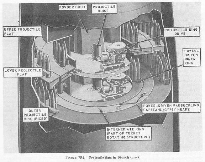
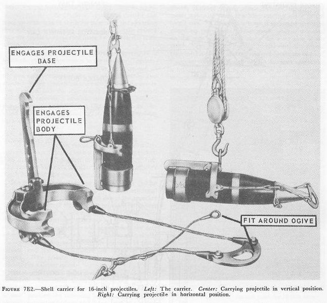
Projectiles are brought to these stowages as follows: First, they land on the main deck in a horizontal position and a shell carrier is fitted around them. An electric drum-type hoist then lowers them in vertical position through hatches alongside the turret to the second platform level. Here they are transferred to an overhead trolley, from which they hang in horizontal position. The trolley takes them under a hatch in the projectile flat, where they are transferred to an electric whip hoist which hauls them (in vertical position) up to the projectile flat to be stowed. The projectiles are lowered and hoisted one at a time; when each projectile reaches the flat, its carrier is removed and sent up to the main deck to be used again. The projectiles are stowed standing on their bases, and each is separately lashed to the bulkhead.
With the projectile rings loaded and ready for use, the inner rotating projectile ring moves projectiles to positions near the hoists. All 3 hoists can be served simultaneously from 1 ring. Loading into the hoists is performed by parbuckling — passing a line around the projectile, leading the line to a power-operated capstan, and sliding the projectile along on its base.
The parbuckling gear can also deliver the projectiles from fixed stowages to the rotating ring. Manual controls with automatic stop arrangements operate the rotating ring through arcs of 30 degrees to facilitate continuous delivery to the hoists. Three projectiles per minute per hoist can be delivered.
7E2. Projectile hoist
Each gun has a projectile hoist which raises the projectiles from the stowage compartments in the turret rotating structure to the breech end of the gun. The hoist (see fig. 7E3) consists of a tube through which the projectile passes base downward, a hydraulic-ram-type lift, and power drive with its associated control. The three tubes pass through the middle rings of the projectile flats and are almost vertical up to the pan floor. From this point the two outboard tubes slope rearward at an angle to the cradles at the upper ends of the tubes. The center tube continues its vertical course, so that at the guns all cradles are equidistant from the breech.
The hydraulic lift consists of a hydraulic cylinder vertically mounted between the decks of the projectile flats, a piston, and a piston rod which connects to a rack in the tube casing. The piston diameter is about 6 inches, and the piston stroke is approximately 8 feet. The hydraulic lift raises or lowers the projectiles one stage per stroke. The distance to the cradle is 4 stages from the lower projectile flat and 3 from the upper.
The hoist contains 2 sets of spring-loaded pawls, 1 set on the rack connected to the hydraulic piston, and the other on the inner wall of the hoist tube. The pawls in each set are spaced one stage apart. The principles of operation of pawl-type hoists were explained in chapter 5. As the piston and rack move up, the lowest rack pawl picks up the projectile base and pushes it upward past the tube pawl at the next stage. Then the rack moves downward with the piston down stroke, but the tube pawl engages and supports the projectile's base. The projectile body forces the rack pawl for the next stage to retract as the rack descends. At the end of the stroke, this pawl is under the projectile, ready to lift it when the rack moves up again. The process repeats until the projectile is at the top of the hoist.
The power drive for each hoist is located on the machinery floor and consists of an electric motor (75 hp), a reduction gear, and the A-end of a hydraulic speed gear. The A-end is directly connected to the hoist cylinder and develops the 700 psi pressure required to lift a full load of 4 projectiles. A solenoid brake on the electric-motor shaft operates to prevent motion of the hoist when there is a power failure.
The main hoist-control system includes duplicate installations of control handles at stations near the hoist-loading apertures in the upper and lower projectile flats, mechanical and electrical interlocks, and audible and visual signals at these stations. Mechanical and electrical interlocks prevent operation of control handles when projectiles are being loaded in the hoist, when there is a projectile in the cradle, or during the ramming cycle.
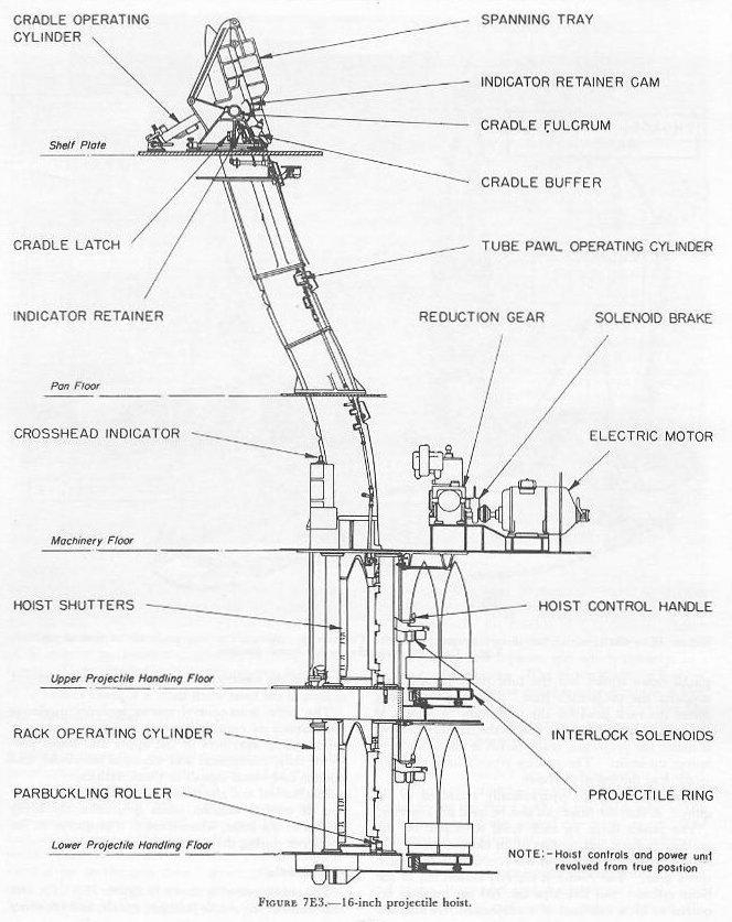
7E3. Cradle
The cradle assembly shown in figures 7E3, 7E5, and 7E6 includes the cradle fulcrum, cradle, and spanning tray. During hoisting the rammer chain is in its retracted position, the cradle is upright so that its axis lines up with that of the hoist tube, and the spanning tray is folded against the cradle. A projectile hoisted into the cradle is supported there by a projectile latch within.
The cradle and spanning tray are operated by a hydraulic cylinder. The control lever for this unit is located at the after end of the gun compartment at the side of the rammer and cradle. When the control lever is operated, the cradle tips forward and the spanning tray moves forward and down, forming a smooth path from the hoist to the chamber. (Fig. 7E5.) The gun must be elevated to 5 degrees for loading, so that the tray lines up with the gun bore.
7E4. Rammer
The rammer consists essentially of a special roller-type chain which meshes with a power-driven sprocket. The arrangement of parts is shown in figure 7E6. The rammer assembly is located in the turret officer's booth just abaft the gun compartment.
The power drive includes an electric motor (60 hp with an overload rating of 108 hp) and a conventional hydraulic speed gear whose B-end drives the sprocket wheel. The control arrangement provides full-power projectile ramming to a jammed stop. This is necessary, since the rotating band must be forced into the rifling so that the projectile will not move to the rear when the gun is elevated. The maximum velocity during the ramming cycle is slightly less than 14 feet a second, and the time required for ramming is 1.7 seconds. The powder bags are rammed into the chamber at a slower speed.
The rammer chain forms a rigid column when it is extended. The chain assembly, including the head link buffer, is about 25 feet long. When in the "ready to ram" position the ramming head is about 8 inches behind the projectile base and 9 feet from the breech face. The projectile travel to full seat during ramming is about 19 feet.


7E5. Powder hoist
The powder magazines are outside the turret foundation on the platform deck beneath the lower projectile flat. The powder is passed manually through self-closing scuttles in the powder-handling room bulkheads and in the lower foundation, into the hoist-loading space around the lower end of the turret revolving structure, and delivered by hoists to the guns.
An electric-hydraulic powered hoist is provided for each gun. Each hoist contains a powder car (fig. 7E4) which rides up and down like an elevator in a closed, inclined trunk which extends through the turret structure from the hoist-loading space to the turret roof. The car is a large box-shaped structure closed on three sides. Four guide wheels, mounted on the rear corners, ride along the after side of the trunk. The bags are carried on two vertically spaced trays which can be separately tilted by means of hand levers on one side of the car. A loaded car delivers a full-service charge of six bags to the gun without intermediate handling.
The car is loaded in the hoist-loading space beneath the projectile flats, through an aperture in the trunk. This opening is sealed by a manually operated, vertically sliding door which must be closed before the car can be hoisted or lowered. It cannot be opened unless the car is in its loading position.
Powder is delivered to the gun through a door located just abaft and to one side of the breech mechanism. The door swings outward and down, providing a shelf across which the powder bags roll from the car to the loading tray. (Fig. 7E5.) The door is operated by a hydraulic power device. When the delivery door is open, the car can be lowered, but not raised. The interlocking features make it impossible to have both the loading and the delivery doors open at the same time.
The hoist power unit consists of an electric motor (100 hp) and a conventional hydraulic speed gear that drives a hoisting drum. The car is lowered by gravity and hoisted by means of a 5/8-inch diameter wire rope which passes over a sheave under the turret top plate and thence to the hoisting drum.
7E6. Loading operation
A 16-inch 3-gun turret can be operated with a minimum crew of 77 men inside the turret. Station assignments for the turret crew are listed in the table below.
| Station | Location |
|---|---|
| Turret officer | Rangefinder and Turret Officer's compartment |
| Turret officer's talker | Rangefinder and Turret Officer's compartment |
| Turret captain | Rangefinder and Turret Officer's compartment |
| Computer operators (2) | Rangefinder and Turret Officer's compartment |
| Rangefinder operator | Rangefinder and Turret Officer's compartment |
| Rangefinder pointer | Rangefinder and Turret Officer's compartment |
| Rangefinder trainer | Rangefinder and Turret Officer's compartment |
| Talker | Rangefinder and Turret Officer's compartment |
| Sight trainer, right; Sight pointer, right; Sight setter, right | Right sight station |
| Sight trainer, left; Sight pointer, left; Sight setter, left | Left sight station |
| Plugmen (gun captains) (3); Cradle operators (3); Rammer operators (3); Primermen (3) | Gun rooms |
| Powder-hoist operators (3) | Top powder trunks |
| Gun layers (3); Gun train operator | Machinery floor |
| Projectile hoist operators (3); Projectile-ring operator; Shellmen (9); Electrician; Shell-deck P.O. | Projectile-handling floor (each level) |
| Powder-door operators (3); Powder passers (9); Handling-room P.O. | Powder-handling floor |
In addition there are 6 powder passers in the annular space between the powder-handling room and the magazines, and 12 powder passers in the magazines.
With the turret in all respects ready to fire and the power machinery in operation, the first command is: "Fill the powder train; fill the projectile hoists." At this command the necessary powder tanks in the magazines are opened; powder is passed through the scuttles to the lower handling room; the powder cars are filled and raised to the top of the hoists. Simultaneously the projectile-handling room crews are loading the projectile hoists with the required type of projectiles.
The first command to the gunroom is "Load." The gun captain, on the loading platform, unlatches the breech operating lever and pushes it down. The primerman, under the breech, assists the gun captain in locking the breech down. The gun captain wipes the mushroom and inspects to see that the bore is clear. As soon as the "Bore clear" signal is given, the gun captain shuts off the gas ejector valve and signals the cradle operator to span the tray (lower it to loading position).
At the same time the primerman inserts a primer into the open firing lock. The rammer operator rams the projectile (Fig. 7E5) until it is seated and withdraws the rammer as he opens the powder hoist door. The powder-car operator tilts 1 of the powder-car trays, and 3 bags of powder roll across the door onto the spanning tray. The gun captain and cradle operator guide the powder bags across the door and space them out on the spanning tray. The powder car lowers about 23 inches and stops automatically, and the remaining three bags of powder are rolled onto the spanning tray.
The rammerman closes the powder-car door and rams the six powder bags to place the rearmost bag not more than 4 inches from the mushroom when the breech is closed. The cradle operator folds the spanning tray as soon as the rammer is withdrawn. The gun captain releases the breech hold-down latch and opens the air valve to the closing cylinder. He then latches the operating lever as the plug rotates to the closed position. The gun captain steps off the loading platform and operates the "ready" switch to signal that the gun is loaded and to bring the gun to gun order position.
F. Turrets Equipped with Case Guns
7F1. General
Propelling charges in metal cartridge cases have a number of advantages over charges in fabric bags. Metal cases are mechanically much sturdier than fabric bags; they don't burn if exposed to a spark or momentary flame; they're much less likely to rupture and spill powder; and the complete propelling charge in its case, including powder, igniter, and primer, can be loaded into the gun in one operation, as compared with the multiple bags and separate primer required for bag-type ammunition. Consequently a turret for case guns can be designed to have a minimum of compartmentation as compared with a bag-gun turret; manhandling of powder can be reduced to a minimum — which means that automatic handling by power gear can be increased to a maximum; extra handling necessary because of the requirements of flametight integrity can be radically reduced. It follows that guns and turrets using case-type propelling charges can be designed to develop much higher rates of fire, and with smaller crews, than can those using bag-type ammunition.
Hence there has been a trend to substitute turrets and guns using case ammunition for those using bag-type ammunition, and at the same time firing rates have increased, the size of crews has decreased, and more and more operations are completely mechanized and made automatic. The ultimate design objective is a turret which, upon signal from a remote station, will train and elevate its guns to a desired position, load its guns, commence firing when the target comes within range, and continue firing until the target is destroyed or all the ammunition expended — all without assistance from operating personnel.
At the present time the Navy has 6-inch and 8-inch case-gun turrets. The earlier 6-inch turrets require in general about as much manhandling of ammunition as does a 5"/38 twin mount. The later types of 6-inch turrets have eliminated manhandling of propelling charges after they have been loaded into the hoist; projectiles still are transferred manually from the hoist upper end into the gun slide. In the newest 8-inch turrets there is no manhandling of ammunition at all after it has been loaded into the hoists.
The remainder of this section will be concerned with the earlier type of 6-inch case-gun turret. The next two sections will take up the newest types of 6-inch and 8-inch turrets.
7F2. Six-inch 47-caliber triple-gun turrets
Light cruisers of the Brooklyn, Cleveland, and Fargo classes are equipped with single-purpose 6-inch turrets of similar designs. The gun has a monobloc, radially expanded barrel with housing and wedge-type sliding breechblock. Ammunition is supplied to the gun room through 1 projectile hoist and 1 powder hoist for each gun, and is transferred by the gun crew from the top of the hoist into a loading tray in the gun slide. Although the maximum elevation of the guns is 60 degrees, loading must be accomplished at an elevation of 22° or less because of the limitations of the ammunition-loading mechanisms and the empty-case ejection system.
The gun compartment is not divided into separate gun rooms, because the inherently greater safety of case ammunition renders such minute flametight subdivision unnecessary. The rear part of the gun house, as in major-caliber turrets, includes the turret officer's booth with rangefinder and equipment for local control of fire. The pointer's and sight checker's stations are located outboard of the left gun, the trainer's and sight setter's stations outboard of the right gun, neither station being separated from the gun compartment by bulkheads.
Levels of the turret below the gun compartment serve the same purposes as in the 16"/50 turret described above. One major simplification is in powder hoist design, the charges for the 6"/47 gun being handled by an endless-chain conveyor-type hoist with open flights instead of powder cars. Elevating and training gear are of electric-hydraulic type and permit a selection of remote or local control.

G. 6"/47 Dual-Purpose Gun and Turret
7G1. General
The main battery of light cruisers of the CL-144 (Worcester) class comprises the newest design now in service of 6-inch guns and turrets. There are 12 guns in six 2-gun turrets, all of them capable of rapid fire against either air or surface targets.

7G2. Turret structure
In general structure these turrets are similar to the 6-inch triple-gun turrets discussed in the preceding section, though there are minor variations (fig. 7G1). The turret foundation is built into the ship and supports the roller path, above which are the gun house and pan floor. Immediately below the pan floor are two projectile-handling levels, then the electric deck, and at the bottom is the powder flat. The barbette extends from just below the gun house to the armor deck. Interior compartmentation is not severe; there are no flametight bulkheads subdividing the gun house, whose space is divided principally by the placement of its equipment and the arrangement of the guns. The gun slides themselves are supported by deck lugs, and these in turn by gun girders and the remainder of the turret structure, as in the other turrets taken up so far.

7G3. Arrangement of turret personnel and equipment
Figure 7G2 shows the arrangement of ordnance equipment and crew stations in the gun house of the 6"/47 turret.
All units of both guns, except the forward portions of the barrels and the power plants for the slide power equipment, are located in the gun house. (The slide equipment motor-pump units are located on the next level, the pan plate.) Also located in the gun house are the upper ends of the 6 ammunition hoists, 2 fuze setting indicator-regulators, all components of the 2 elevating-gear drives and their indicator-regulator controls, and the 2 gun captain's control panels.
Other major units in the gun house are the components of the fire control equipment. These are grouped into three stations: the right and left wing stations (also called sight stations) and the turret officer's booth. The right wing station includes controls for the turret trainer and for the right gun pointer and sight setter; the left station includes controls for the checker (standby turret trainer) and for the left gun pointer and sight setter. The turret officer's booth includes the controls for the turret officer, turret captain, radar control operators, and computer operator.
Twenty-one members of the crew are located on the shelf plate of the turret; 10 in the turret officer's booth and 11 in the gun house. These comprise 11 turret controlmen, 3 gun-laying operators, 3 gun operators, 2 hot-case men, and 2 projectile loaders.
The pan plate contains most of the components of training gear drive and the hydraulic power supply for the slide power equipment, as well as some of the equipment for the hoist power drives.
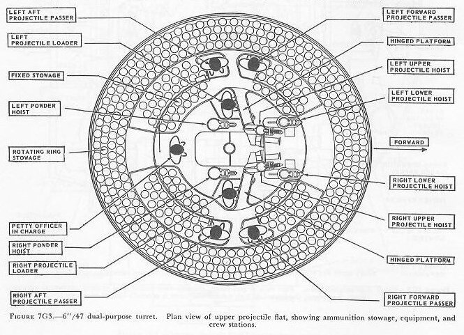
The projectile-handling floor is divided into upper and lower projectile stowage flats. Figure 7G3 shows the upper flat. The lower flat is generally similar, except that its diagram would show only 4 hoists (2 powder and 2 projectile) instead of the 6 visible in figure 7G3. This turret has but 1 projectile ring assembly, but the ring has 2 tiers, 1 for each flat. Each tier is set up to stow 288 projectiles. Fixed stowage capacity is 106 projectiles at the upper level, and 124 at the lower.
The same crew of 7 operates on either the upper or the lower flat. It consists of a petty officer in charge and 1 projectile loader and 2 passers for each hoist being served. The loaders merely shove projectiles into the hoists, which start automatically when loaded.
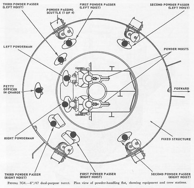
At the powder-handling room level, four powder-passing scuttles admit powder cases from the magazine. A crew of 9 operates in the powder-handling room — 6 powder passers taking the charges from the scuttles to the powder hoists, 2 powdermen operating the scuttles at the foot of the hoists, and a petty officer in charge (fig. 7G4).
7G4. Gun assembly
The right- and left-hand gun assemblies are functionally identical, though some parts are of opposite hand. The two gun assemblies are symmetrically arranged about the turret centerline.
The 6"/47 gun used in these turrets is a monobloc radially expanded type, designed for semifixed ammunition, whose bore has 48 rifling grooves with right-hand uniform twist, 1 turn in 25 calibers.
The gun housing has a vertically sliding breech-block operated by a hydraulic cylinder, and a single spade extractor, also hydraulically operated (fig. 7G5).

The firing mechanism is designed primarily for electric primers, but it provides for percussion firing of short cases. The breech and firing mechanism and their power-operated components normally function automatically when the gun is firing, but they can be operated manually or by power under manual control.
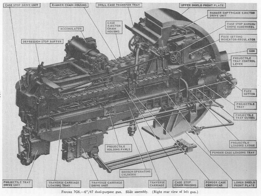
7G5. Slide, rammer, and case ejector
Figure 7G6 shows the slide of the left gun. Mounted atop the slide is an accumulator from which is distributed the hydraulic fluid that operates the case extractor and breechblock in the gun housing and the projectile tray, case stop, traverse carriage, and ammunition rammer-empty case ejector in the slide.
The projectile is manually loaded into the projectile tray, and the powder case is mechanically loaded into the powder-case loading tray. The projectile tray drive unit then drives the projectile tray and fuze setter head aft. The powder-case crosshead, which is mechanically linked to the case-stop drive, engages the base of the case in the powder-case loading tray. The case stop drive for most of this operation is set to function as a braking unit; thus the projectile tray drive unit during most of its stroke aft drives the projectile and powder case against the braking effort, exerted through the powder-case crosshead, of the case-stop drive unit. This keeps the projectile's nose firmly inside the fuze-setter pot. The fuze is set during this operation.
At the end of this stroke the complete round is in the traverse carriage loading tray. The traverse carriage has two positions: FIRE position, with the empty-case tray lined up with the gun bore to receive the empty case upon extraction; and RAM position, with the loading tray lined up with the bore.
7G6. Ammunition hoists
Each gun is served by three ammunition hoists: one powder hoist, and two projectile hoists (one projectile hoist from each of the two projectile flats). The powder hoist delivers the powder cartridge directly to the gun slide completely automatically, regardless of the movement of the gun in elevation, without manhandling of the case, and without requiring that the gun be brought to a specific loading position. The projectile hoists bring the projectiles to a point adjacent to the slide, from which they are manually transferred to the gun slide.
All six ammunition hoists are generally similar. All are of the continuous type in which an endless-chain conveyor, operating intermittently, automatically starts hoisting every time the hoist lower end is loaded, until the hoist is full. Each hoisting cycle lifts the projectile or powder case one stage. The hoists can also be reversed for lowering ammunition.
The powder hoist lower end is fitted with a flameproof scuttle for extra safety. The upper end terminates in a power-driven cradle which automatically loads the propelling charges into the gun slide.
7G7. Fire control and power drive equipment
The 6"/47 dual-purpose turret is designed to deal with air as well as surface targets. It is capable of a maximum surface range of over 25,000 yards, and can reach targets at an altitude of over 51,000 feet when at its maximum elevation of 78°. There is no optical rangefinder in these turrets, but they are equipped with telescopic prismatic sights, periscopes, and sight-setting equipment, as well as radar and computer equipment.
The turret is driven in train and the guns in elevation by electric-hydraulic power drives controlled by receiver-regulators. The fuze setters on the gun slides are also operated by receiver-regulators. There are six designated types of turret control:
1. Primary surface control. The gun and turret drives are controlled by an aloft radar antenna mount or by an aloft main-battery gun director, operating in conjunction with main-battery plotting room equipment.
2. Primary AA control. The gun and turret drives are controlled by an aloft main-battery gun director operating in conjunction with main-battery plotting-room equipment.
3. Secondary surface or AA control. The gun and turret drives are controlled by a 3-inch battery director.
4. Local radar control. The drives are controlled by the radar equipment within the turret, with the pointers controlling gun laying with their sights and handwheel controls.
5. Hand control. The gun-laying and training drives are controlled by the pointers and selected trainer using their sights and handwheel controls.
Unlike other 6-inch turrets, the elevating gear is of the arc-and-pinion type (same principle as the 5"/38 mount) instead of the screw-and-nut type (like that in the 16"/50 turret).
7G8. Other facilities
The 6"/47 dual-purpose turret is fitted with the usual electrical illumination, power, data-transmission, alarm, signal, and communications circuits. It is equipped with 2 compressed-air pipe systems — one a 125-psi system for supplying air to the gas ejector and sprinkling systems, and the other a 3,000-psi supply for the counterrecoil air-replenishing system. The turret also has 2 self-contained exhaust systems for the empty-case ejectors and 2 ventilating systems which supply air under forced draft to all turret levels. It is equipped with an elaborate sprinkling system which can spray water at all ammunition stowage points as well as in the ammunition hoists and at the gun breeches.

7G9. Turret operation
When the ammunition hoists are filled, a powder case goes into the cradle and a projectile goes into the projectile hoist upper end. When the powder cradle receives a powder case from the hoist, it automatically rises, latches to the slide, and ejects the case into the slide loading tray (fig. 7G8).
The projectile loader then manually transfers the projectile from the hoist to the slide. With both the powder case and the projectile in the slide, the projectile loader pulls down the projectile-tray control lever to start the projectile tray and fuze-setter head moving aft.
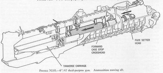
The tray and fuze setter force the projectile and case to the rear of the slide against the braking action of the case stop (figs. 7G9, 7G10, and 7G11). The forward crosshead of the case stop holds the projectile nose seated in the fuze-setter head, and the fuze setter functions to set the fuze as the projectile travels aft.
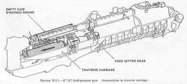
After the ammunition has moved all the way aft into the traverse carriage (fig. 7G11), the fuze-setter head remains in contact with the projectile fuze until the empty case from the previous round has been extracted and is latched in the empty-case tray.


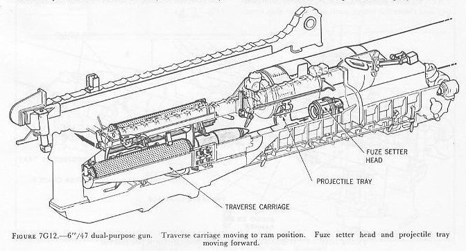
The projectile tray and fuze setter head then move forward, clearing the traverse carriage (fig. 7G12). This allows the traverse carriage to start toward ram position. The traverse carriage continues toward ram position and clears the return path of the case-stop crossheads. The powder cradle, during the previous ammunition movements, has received another case, raised it, and latched to the slide ready for the next cycle.
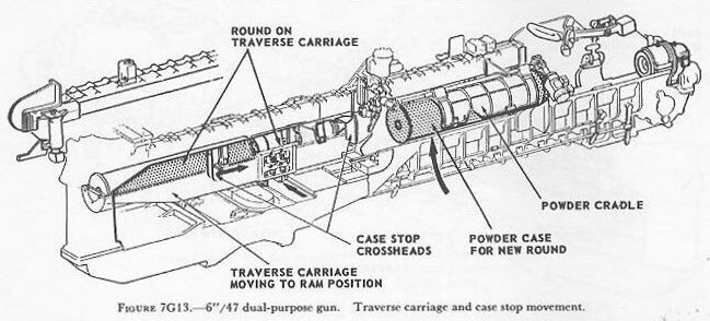
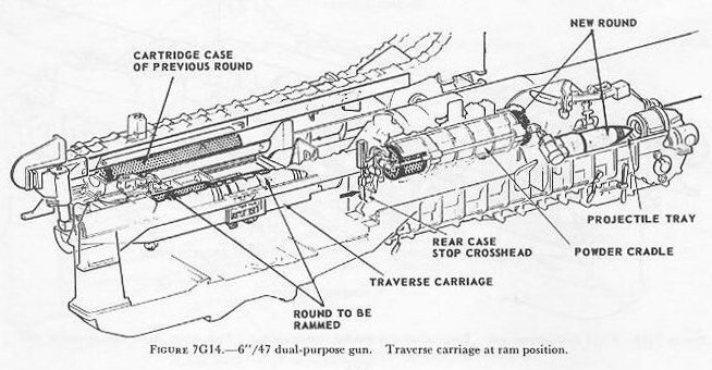
As the traverse carriage reaches ram position, the projectile tray is forward and the case stop is nearing its forward position (fig. 7G13). The rear case-stop crosshead, upon reaching its forward position, initiates the powder-case ejection from the cradle to the slide loading tray (fig. 7G14).
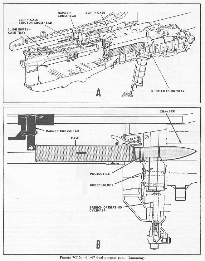
Next, the rammer drives the round into the chamber. At the same time, the empty-case ejector crosshead pushes the empty case from the preceding round from the traverse carriage empty-case tray into the slide empty-case tray. Figure 7G15 (A) shows the operation of slide units in ramming. Figure 7G15 (B) shows the ramming action from a slightly different point of view — a cross-section view of the round being rammed past the breechblock into the chamber.
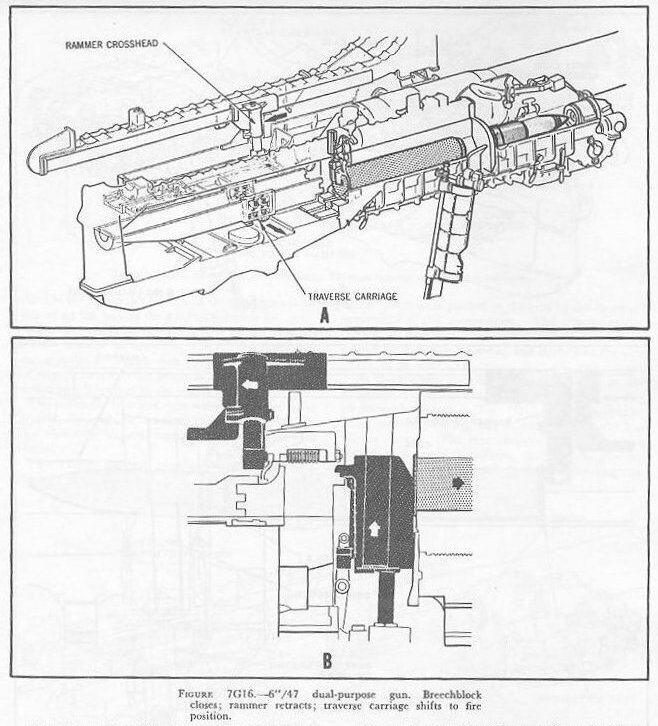
When the rammer crosshead reaches the end of the ram stroke, the traverse carriage shifts back to fire position (fig. 7G16 (A)). At the same time, the breechblock starts closing. When the block has moved up far enough to hold the ammunition in the chamber, the rammer retracts (fig. 7G16 (B)). When the breechblock has risen to its fully closed position, it is locked by the breech bolt, and the firing pin of the cocked firing mechanism contacts the primer of the powder case.
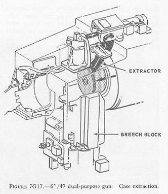
When the gun fires, it moves in recoil and counterrecoil under the control of the recoil brake and recuperator mechanism. During the counterrecoil stroke the breechblock is mechanically unlocked; a valve ports hydraulic fluid to the breech operating cylinder to lower the block shortly before the end of the counterrecoil stroke. When the breechblock is hauled down to its fully open position, the fired case is extracted from the chamber (fig. 7G17) and is thrown aft into the traverse carriage empty-case tray.
The hot-case man picks up the case from the slide empty-case tray and drops it into a power-driven conveyor (the empty-case ejector), which sends the empty case out through a door in the rear of the turret.
H. 8"/55 Rapid-Fire Gun and Turret
7H1. General
At the present time the closest approach to the completely automatic turret described earlier in this chapter is the 8-inch 55-caliber rapid-fire gun and turret. These are the largest United States naval weapons now in service using case ammunition. Three such turrets are installed on Salem class heavy cruisers.
In this type of 8-inch turret, structural and space arrangement plans differ substantially from those of bag-gun turrets like the 16-inch turrets taken up earlier in this chapter. They are equally different from 8-inch bag-gun turrets on cruisers of similar type (for example, Baltimore class). This difference is due in part to the use of case-type ammunition, and in part to the design types and details of the guns and ammunition-handling equipment. The ammunition and equipment designs do not require flameproof bulkheads separating the guns, the control stations, and the powder service.
The foundation structure, barbette, and magazine designs are quite similar to those of earlier heavy cruisers, differing principally in the magazine stowage provisions and powder-passing scuttles for powder cases instead of powder bags.
In their ordnance features, however, the turrets are entirely new. The guns operate automatically, and require no attendants in the gun compartment. They fire at three times the rate of the comparable 8-inch three-gun turrets of the Baltimores. Other features are: comparatively fast gun laying and turret train drives; loading at all angles, while gun laying; substitution of radar range-taking equipment for optical rangefinder; automatic fuze setting; local radar control; and other flexible fire control arrangements for local and remote control.
7H2. Structure and space arrangement
As with earlier designs, the fixed-turret structure includes a foundation which supports a roller path, and an armor barbette which protects all levels of the turret between the armor deck and the gun house. The rotating structure is topped by a gun house; under this, the levels are the pan plate (which forms the bottom of the gun pits), two projectile flats, and a powder-handling room. There is no separate electric deck; the equipment that usually occupies such a deck is mostly inside the circular bulkheads that enclose the central part of the turret at the projectile-flat levels (figs. 7H1 and 7H2).


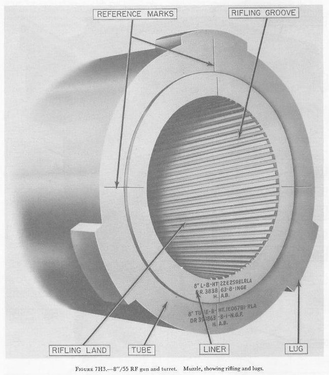
7H3. Gun
The gun is a combination type, 2-piece, 8-inch 55-caliber design consisting of a tube and rifled liner. It is a "loose" assembly. The liner is fitted for convenient removal and replacement on board ship. It is designed to withstand a pressure of nineteen long tons per square inch. Its rifling is of uniform right-hand twist with 64 grooves and 1 turn in 25 calibers. The powder chamber and breech are designed for semi-fixed ammunition.
Figure 7H3 shows the muzzle details, including the three lugs which anchor the jacks that are used to haul out the liner for replacement.
7H4. Gun supporting elements
The gun supporting structures are of the usual turret type — gun girders (fig. 7H2) which support the deck lugs (fig. 7H4) into which the gun slide trunnions fit. The slide trunnions pivot in roller bearings in the deck lugs (fig. 7H4).
The trunnion arrangements of the slide include journals for mounting two cradle units. These are the upper ends of the ammunition hoists.

7H5. Gun housing and breech mechanism
Figures 7H5 and 7H6 illustrate the anatomy of the housing and breech mechanism with the breech open and closed. The gun housing is a rectangular alloy steel forging. It is attached to the gun shoulder and rear cylinder by a bayonet-type joint. The housing has vertical guide ways for the breechblock. The guides have a slight forward slope to make the breechblock seat the projectile as it rises.
The breech mechanism consists of a vertically sliding power-operated breechblock, an electric firing mechanism, a power-operated mechanical case extractor, hydraulic cylinders and valves to drive these components in normal breech operation, and manually operated mechanisms to supplement the power system.
The breechblock is a rectangular steel forging similar in general design to other vertical sliding breechblocks. Its top surface has a longitudinal concave area that forms an extension of the ramming tray (fig. 7H6). A horizontal fore-and-aft bore through its middle houses the firing pin assembly. The breechblock is moved vertically in the housing ways by a hydraulic cylinder. When closed (top position, as in figure 7H5), it is locked by a spring-loaded rectangular bar — the breech bolt.
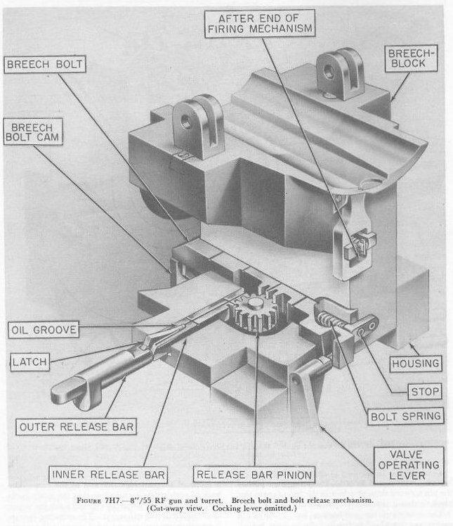
The breech bolt is released from this position by a rack-and-pinion gear arrangement (fig. 7H7) actuated by an inner release bar during the automatic cycle. The breech bolt and bolt cam together perform this locking operation, plus that of retracting and holding the firing pin when the breechblock is not closed.
The firing pin assembly (fig. 7H5) extends longitudinally through the breechblock. It is for electrical firing only, though it can be rigged for percussion firing in emergency. The spring-loaded firing pin is retracted by the cocking lever (fig. 7H6) until the breech is closed and locked. Its spring then pushes the pin forward through a hole in the front face of the block so that it contacts the powder-case primer.
The case-extractor mechanism has 2 extractor spades, operated by 2 hydraulic cylinder units bolted on top of the gun housing (fig. 7H6). In normal operation, the extractor functioning is controlled by electrical switches and solenoids actuated by the breechblock as it nears the bottom of its downward movement.


7H6. Slide and slide power equipment
The gun slide (fig. 7H8) supports the gun in a cylindrical bearing and two parallel rails. The slide is fitted with a hydraulic recoil brake and hydropneumatic recuperator. The slide trunnions fit into bearings in the deck lug. The slide also contains power-operated units which accept ammunition from the hoists, ram it into the chamber, and dispose of extracted cartridge cases.
The slide power equipment includes the breech operating mechanism, the ammunition transfer trays, and the rammer and case-ejector hydraulic operating units, all of which receive hydraulic fluid from a hydropneumatic accumulator. This unit consists of a large vertical cylinder and two air flasks mounted at the side of the slide. An extensive system of hydraulic pipes connects it to all operating units and to a pump mounted with its electric motor on the upper projectile flat. This system continuously delivers power throughout all gun-loading and gun-firing operations.
Hydraulic power operations of the gun units are controlled by limit and interlock switches and valve-operating solenoids, and control switches of the gun captain's control panel in the turret officer's booth. This gun-loading control system enables all loading and firing actions to be performed without attendants in the gun compartment and during gun-laying movement.

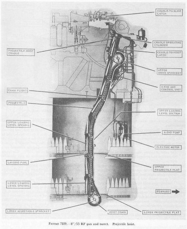
7H7. Ammunition hoists
Each of the three guns of the turret has a projectile hoist on its right and a powder hoist on its left. Both kinds of hoist are of the electric-hydraulically driven endless-chain and sprocket type, and in principle resemble the dredger hoist used in 5-inch mounts. Since the projectile and powder hoists are similar in general construction and principle, only the projectile hoist is shown in the figures (fig. 7H9).
The upper end of each hoist terminates in a cradle — a tubular unit suspended from a journal on the slide trunnion and arranged to swing between the top of the hoist and the side of the slide. When the cradle swings up to the slide, it latches there and moves with gun-laying action until the projectile or powder case is ejected. Then it moves to the hoist, and latches in alignment with the hoist tube, permitting the hoist to feed it another projectile or powder case.
Each cradle has a pawl at its open end and a large spring-ram device at the trunnion end. When the hoist lifts a projectile into the cradle, the spring ram is compressed and a pawl latches the projectile so that it cannot move out unless the pawl is depressed. A remotely controlled fuze setter is located in the projectile cradle.
The powder hoist has, at its lower end, a flameproof scuttle consisting of a revolving cylinder with two compartments 180° apart. When one compartment faces into the hoist tube, the other faces outward. An electric drive controlled by a crewman rotates the cylinder 180° when a powder case has been loaded into the outer compartment, to transfer the case inward to be hoisted.
7H8. Ammunition-handling operations
Each 140-pound metal powder case contains the complete propelling charge for an 8-inch gun. The cases are moved in small trucks, rather than by hand carrying.
The powder-handling room is not divided by flametight bulkheads, but forms one large enclosure. Propelling charges are transferred from the magazine through the powder-handling room bulkhead by rotary scuttles. Crewmen load the charges into hand trucks, push them to the hoists, and unload them into the rotary scuttles at the powder-hoist lower ends.
The projectile hoist can be loaded at either projectile-flat level. Projectile hoist operation is normally completely automatic. Loading the hoist automatically starts its hydraulic drive to raise the ammunition one flight (if the empty cradle is waiting at the upper end).

Figure 7H10 illustrates the projectile ring and parbuckling gear layout in the Salem class turret. Inside the turret foundation bulkhead are: (1) the outer projectile ring (capable of independent rotation); (2) the outer projectile-handling platform with right and left projectile hoists; (3) the inner projectile ring (independently driven); and (4) the central part of the turret rotating structure with the center projectile hoist. Only the two projectile rings are used for projectile stowage.
7H9. Gun-loading equipment
Most of the loading machinery that serves ammunition to the 8"/55 RF gun is shown in figure 7H11. The projectile-hoist cradle, which receives the projectile from the projectile hoist, can swing up and down (arrow A) between its hoist or receiving position (aligned with the hoist) and its discharge position, aligned with the tubular projectile transfer tray. The cradle is rotated on a journal bearing surrounding the trunnion by a hydraulic cylinder. The cradle locks in either position, regardless of gun elevation angle, and regardless of whether or not the gun is moving in elevation. There is a similar powder-hoist cradle on the left trunnion.
The powder transfer tray and projectile transfer tray, when swung outboard as in figure 7H11, are in firing position. These trays can swing inboard, under the thrust of hydraulic cylinders, to ramming position, in which they are aligned with each other, with the gun breech, and with the rammer.

7H10. Operating cycle
Following is the sequence of operations in normal automatic operation, beginning with the hoists full, and with gun-loading equipment in the positions shown in figure 7H11.
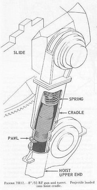


1. Hoists load cradles. The projectile and powder hoists lift a projectile and powder case into their respective cradles, compressing a heavy coil spring in each (fig. 7H12). Spring-loaded pawls hold the projectile and case in the cradles.
2. Cradle movement to discharge position. Each cradle swings upward to discharge position, automatically latching in alignment with the transfer tray (fig. 7H13).
3. Transfer to transfer tray. When the powder cradle reaches this position, interlock switches close a circuit which causes immediate hydraulic retraction of the retaining pawl. The compressed coil spring in the cradle thereupon throws the powder case into the transfer tray. Operations on the projectile side are similar, except that retaining pawl retraction is synchronized to occur only when the breech is open (fig. 7H14). This delayed delivery reduces fuze dead time.
4. Transfer trays to ramming position. The two trays are hydraulically swung into ramming position, and the powder case and projectile are properly positioned for ramming (fig. 7H15).
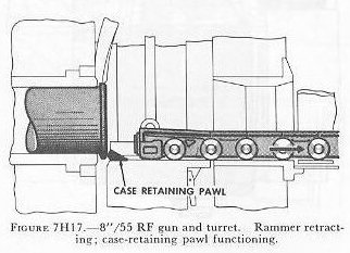
5. Ramming. When the trays are lined up with the open breech and the rammer (fig. 7H16), the rammer rams the projectile and powder case into the gun chamber, then automatically reverses and retracts. The spring-loaded pawl at the top of the breechblock engages the cartridge-case rim to prevent the case from sliding rearward (fig. 7H17).
6. Breech closing (fig. 7H18). When the rammer chain has cleared the breechblock, the block rises. Breechblock movement wedges the powder case into the chamber.
7. Breech locking (fig. 7H19). Positive stops limit breechblock closing movement at a position that synchronizes with the end of bolt travel on the bolt cam. The spring-loaded bolt moves forward across the top of the cam to breech-locked position, and the firing mechanism moves to firing position.
8. Gun firing. In its firing position, the pin is in contact with the primer of the powder case. As the firing circuit is closed, the current ignites the primer and the powder charge.


9. Gun recoil, counterrecoil, and breech opening. During counterrecoil a cam in the slide causes two push bars to rotate the gear in the block and retract the breech bolt (fig. 7H20). This retracts the firing pin, unlocks the block, and causes the breechblock cylinder valves to port hydraulic fluid into the cylinder to lower the block.
10. Case extractor operation. As it nears full open position, the breechblock actuates a valve that admits hydraulic fluid to the extractor hydraulic cylinder. In full open position, the top of the breechblock is below the path of the empty powder case when it is extracted (fig. 7H21). Both extractors move to extract the case and eject it to the rear (fig. 7H22). Then they retract.
11. Gas ejector operation. When the case extractors are actuated, a mechanical linkage opens the blow valve of the gas ejector, porting air via the pilot valve to three orifices in the breechway. The air automatically shuts off.
12. Breechblock to loading position. The breechblock moves upward approximately 0.75 inch to gun-loading position.
13. Empty-case tray operation. As the empty case comes out of the chamber (fig. 7H23), the guide keeps it from being thrown out of the slide. The hydraulic buffer takes the impact of the case, and the two retaining latches hold it in place in the empty-case tray. By now the powder and projectile trays have been reloaded. Arrival of the empty case in its tray actuates 1 of a series of interlocked electric switches, and the 2 reloaded trays move toward ramming position once more. As the powder-case tray swings downward, so does the empty-case tray (fig. 7H24). The case-retaining latches are cammed open, and the empty case is dumped into the case-ejection mechanism under the gun slide.
14. Case ejector action. The case ejector consists principally of a sprocket-driven endless chain with two equally spaced pawls, and a tube leading outside the turret under the gun (fig. 7H25). When the empty case lands on the ejector, it depresses a pawl which closes a switch; the case-ejector drive moves the chain forward one flight. As the chain moves forward, 1 of its 2 pawls pushes the powder case into the tube. Since the capacity of the empty-case tube is only five cases, eventually the cases at the front end are ejected past the door out to the ship's deck (fig. 7H26).


7H11. Training and elevating gear
The guns of this turret are laid by arc-and-pinion type elevating gear. The training gear is similar to that of other turret installations. The training units include the training gear electric-hydraulic drive equipment, a train receiver-regulator, and control station equipment for the turret training system. There are 3 elevating gear assemblies, 3 gun elevation indicator-regulators and power drives, and 1 pointer's control station equipment for the gun elevating system.
Turret training and gun laying are controlled much as in the 6"/47 dual-purpose turret described earlier in this chapter. The pointer's and trainer's control equipment provides for three methods of control — automatic, local, and hand. In automatic, the electric-hydraulic train and elevation power drives are under the immediate control of the fire control directors. In local, the power drives are controlled through the receiver-regulator or indicator-regulators by the trainer's and pointer's handwheels. In hand control, the receiver-regulator and indicator-regulators are bypassed, and the trainer's and pointer's handwheels directly control A-end tilt to regulate the functioning of the elevating and training power drives.
7H12. Fire control
In general, fire control arrangements are quite similar to those possible with the Worcester class 6"/47 turrets described in the preceding section. The turret battery can be controlled by main-battery directors through forward or after plot, or by the secondary-battery directors. Turrets II and III have their own radar equipment for determining target location, including range. Turret II can function to aim the guns of turret I. Each turret can also function in local control.
7H13. Crew stations and operations
Forty-four men are required to man the battle stations of this turret installation. Twenty-seven men of this complement, located in the levels below the gun house, operate the ammunition service to the guns; six others, stationed in the gun house, control and maintain gun operations; these 33 men are identically employed in all methods of turret control.
The balance of the organization consists of 2 gun-laying operators and 10 turret controlmen, all stationed in the gun house. In fully automatic operation, the operations of the guns are controlled from the turret officer's booth in the rear of the turret from control panels and switchboards.
Eighteen members of the crew are located in the gun house (fig. 7H27): 10 turret controlmen, 2 gun-laying operators, and 6 gun operators. The 10 turret controlmen are the turret officer, turret captain, computer operator, 2 radar operators, 3 talkers, sight setter, and checker. The two gun-laying operators are the pointer and trainer. The 6 gun operators are the 3 gun captains, their assistants, and the electrician.
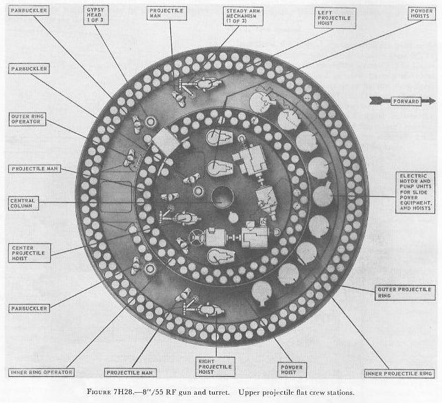
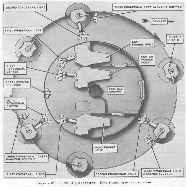
Eight members of the turret organization are stationed in the upper projectile flat (fig. 7H28). They are all engaged in supplying projectiles to the hoists, with the ring operators maintaining supply to all. The lower flat is set up similarly, except for an additional crewman — a roving electrician with maintenance duties (fig. 7H29). Ten men conduct the powder transfer service; three men serve each hoist under supervision of a petty officer.