
Chapter 12 of Naval Ordnance and Gunnery, Volume 1 (NavPers 10797-A, 1957) covers the design, construction, and operation of U.S. Navy torpedoes. Using the Mark 15 gas-steam torpedo as the primary example, the chapter traces every major system—head section and exploder, air and superheating systems, main engine, gyro and depth-control mechanisms, and tail section—then addresses aircraft torpedoes, other fleet types including electric and homing models, and above-water torpedo tube mounts.
A. Introduction
12A1. General
A torpedo is a self-propelled underwater weapon that carries a high-explosive charge to its target. A torpedo can do more damage than a projectile from the biggest guns on a battleship. There is more explosive in a torpedo war head than there is in any projectile.
The torpedo war head explodes under water, and that increases its destructive effect. When a projectile explodes, a part of its force is absorbed by the surrounding air. But when the torpedo war head explodes, the water transfers almost the full force of the explosion to the hull of the target ship. Thus, even if a projectile could carry the same amount of explosive, the torpedo would do more damage.
The torpedo makes it possible for small ships to carry heavy armament. But of course it can not make a small ship the equal of a large one in combat. A torpedo moves slowly compared to a projectile, and its effective range is much shorter.
12A2. Applications
The torpedo is an important weapon of destroyers, destroyer escorts, and frigates. Torpedoes are the principal armament of PT boats and submarines, and, under certain conditions, of aircraft. The tactical use of torpedoes is gradually changing; their use in surface engagements is less frequent than it was a number of years ago. The outcome of a battle is likely to be decided before the enemy is within torpedo range. Even so, the ability of a destroyer to launch torpedoes serves as a constant threat to the enemy, and thus limits the range of maneuver available to him.
When an aircraft approaches a surface ship within torpedo-launching range, it is vulnerable to antiaircraft fire. In future warfare, it is likely that both destroyers and torpedo planes will use guided missiles against surface targets. The missiles will carry torpedoes to within launching range of the enemy.
While it is submerged, a submarine is not vulnerable to gunfire. A submarine can often approach within torpedo range of its target before its presence is detected. Torpedoes will therefore continue to be the principal armament of submarines in the foreseeable future.
Homing torpedoes are a relatively recent development; they have been perfected since the end of World War II. With homing torpedoes, a destroyer can attack a submerged submarine, even when its exact position and depth are unknown. The homing torpedo is becoming increasingly important as a weapon with which one submerged submarine may attack another.
12A3. Launching methods
There are two principal ways to launch a torpedo—by firing it from a tube, or by dropping it from a rack.
PT boats launch torpedoes from racks at the sides of the boat. A PT boat may carry from 2 to 4 torpedoes.
Aircraft drop torpedoes from launching racks; usually, an aircraft carries only a single torpedo.
Older destroyers carry 5 torpedoes, in a tube mount that consists of 5 barrels side by side. The tube mount is carried amidships. It can be trained through a wide arc, so that torpedoes may be fired from either side of the ship. Impulse charges of black powder are used to expel the torpedoes from the tube mount with enough force to clear the firing ship.
Newer destroyers, destroyer escorts, and frigates are fitted with fixed, non-trainable tubes—usually four of them. The tubes are located below the weather deck with their muzzles extending through the sides of the deck house. Torpedoes are expelled from these tubes by compressed air.
Submarines fire torpedoes from fixed, below-water tubes. The fleet-type submarine is fitted with 10 tubes—6 in the bow and 4 in the stern. On firing, the torpedoes are expelled from the tubes by compressed air. Spare torpedoes are carried in ready racks near the tubes. A submarine on war patrol will usually put to sea with a load of 28 torpedoes aboard.
12A4. Requirements of a torpedo
As previously stated, a torpedo is a self-propelled weapon. Its principal requirements are, therefore, a charge of explosive and a power plant. As a practical weapon, a torpedo must have a number of other features. These include the following:
A shell, or housing, strong enough to support the explosive charge, power plant, and related mechanisms, and strong enough to withstand the shock of launching.
A source of energy for the power plant, and for the torpedo control mechanisms.
An exploder that will detonate the explosive charge when the torpedo reaches its target, but which will remain inoperable while the torpedo is close to the firing ship.
Control mechanisms that hold the torpedo on a preset course, at a preset depth.
One or more propellers to drive the torpedo through the water.
Tail vanes and rudders, to control course and depth. Sections B through G of this chapter will show how these requirements are met in a typical torpedo—the Mark 15 type.
12A5. Types of torpedoes in service
All torpedoes are similar in general appearance; they are typically cigar-shaped, as shown in figure 12A1.

Torpedoes may be classified in several ways:
1. By their power plants (gas-steam or electric). Electric torpedoes are powered, of course, by electric motors; the energy source may be either a dry battery or a lead-acid storage battery. The power plant of a gas-steam torpedo consists of a pair of turbines and a gear-reduction engine. In most of the gas-steam torpedoes, energy is provided by compressed air and alcohol. In the Mark 16 type, the energy source is alcohol and a concentrated solution of hydrogen peroxide.
2. By the craft from which they are launched (destroyer, submarine, or aircraft).
3. By their speed and range.
4. By the type of exploder. The impact exploder operates only when the torpedo actually strikes its target. The influence exploder (which will not be described in this volume) operates when the torpedo passes near its target.
5. By the type of control mechanism. In the older torpedoes, the control mechanism holds the torpedo on a previously calculated collision course with the target. The homing torpedo (which is described briefly in article 12I6) can steer itself toward its target and, if necessary, chase it.
The following list summarizes the characteristics of the nonhoming torpedoes now in the Fleet.
Mark 13 type. The Mark 13 torpedo, compared with the others, is short and thick: its length is 13½ feet, and its diameter, 22½ inches. (The others all have the same diameter—21 inches—so they will fit the standard torpedo tubes.) The Mark 13 is designed for launching from aircraft and PT boats. Its range is 6,000 yards at an average speed of 33½ knots, and it carries 600 pounds of high explosive.
Mark 14 and 23 types. The Mark 14 torpedo is fired from submarines. Its length is about 20½ feet. It offers a choice of two speeds. At the high-speed setting it has a range of 4,500 yards, at an average speed of 46 knots. At the low-speed setting its range is 9,000 yards, and its average speed is 32 knots. It carries 600 pounds of high explosive. The Mark 23 torpedo is exactly like the Mark 14, except that it has no speed-change mechanism. It operates only at high speed.
Mark 15 type. The Mark 15 torpedo is launched from the deck tubes of surface ships. It is 24 feet long, and carries an explosive charge of about 800 pounds. It has three speeds: 26½ knots (range 15,000 yards); 33½ knots (range 10,000 yards); and 45 knots (range 6,000 yards).
Mark 16 type. The Mark 16 is a “chemical” torpedo. It uses a strong solution of hydrogen peroxide, rather than compressed air, to support the combustion of its fuel. This feature gives the Mark 16 a relatively high speed and long range, and enables it to carry a relatively heavy charge of explosive.
Mark 18 type. The Mark 18 is the only nonhoming electric torpedo now in the Fleet. Its principal source of energy is a large lead-acid storage battery. It has a length of about 20½ feet, and an effective range of 4,000 yards at an average speed of 29 knots.
12A6. Construction of the gas-steam torpedo
A gas-steam torpedo is made up of five sections—the head, air-flask section, midship section, afterbody, and tail. Figure 12A1 is an external view of a Mark 15 type torpedo, showing the four principal sections. The midship section, which is not indicated in the figure, is very short; it is located at the after end of the air-flask section. Because it is permanently joined to the air flask, it is not always counted as a separate section.
When a torpedo is issued to the Fleet it consists of three main units: (1) the head; (2) the air-flask and midship sections (permanently joined); (3) the afterbody and tail (assembled together with joint screws).
Figure 12A2 is a cutaway view of a Mark 15 type torpedo, showing the principal contents of the various sections.
The war head contains the charge of high explosive, and the exploder mechanism that detonates it. The air-flask section contains the air flask, fuel flask, and water compartment. In the midship section are a number of valves and fittings for transferring fuel, air, and water between the air-flask section and the afterbody, and for recharging the air flask. Also in the midship section, but attached to the afterbody, is the combustion flask. In this flask, compressed air and fuel are mixed and burned, and provide a high-speed stream of exhaust gases to spin the turbines. Water is sprayed into the combustion flask to increase the volume of gases that go to the turbines, and to prevent overheating.
The contents of the afterbody include the turbines and gear-reduction engine, and their lubrication system; the starting gear; and the mechanisms that control the course and running depth of the torpedo. The depth mechanism includes a diaphragm and pendulum, which determine the torpedo’s depth and the inclination of its axis, and a depth engine to control the depth rudders. The steering mechanism includes a gyro to determine the torpedo’s actual course with respect to the preset course, and a steering engine to control the action of the steering rudders.
The mark of a gas-steam torpedo applies to the air flask, afterbody, and tail. The war head, exercise head, and gyro have individual marks.

B. Head Section of a Mark 15 Type Torpedo
12B1. General
The head section may be either a war head or an exercise head. The war head is almost entirely filled with high explosive. The exploder is mounted in a cavity on the lower surface of the war head shell. For a test shot, or for firing practice, an exercise head is used in place of the war head. The exercise head contains no explosive charge, and no exploder mechanism. For an exercise shot, the exercise head is filled with a liquid ballast—either water or a solution of calcium chloride. At the end of an exercise run, the liquid ballast is automatically expelled. When the head is empty, the torpedo has enough buoyancy to float until it can be recovered.
12B2. Functional description
The war head shell serves simply as a container to house the high-explosive charge and the exploder mechanism. Since the main charge of explosive is relatively insensitive to shock, an exploder mechanism is needed to detonate the main charge when the torpedo strikes the target. The exploder mechanism is so designed that, on impact with the target, it explodes a small detonator charge. The detonator then explodes a booster charge, which in turn detonates the main charge.
When the torpedo is launched, the exploder mechanism is in a “safe” condition. It cannot explode the booster charge, even if its detonator explodes accidentally. During the first few hundred feet of the torpedo’s run, the exploder mechanism arms itself. When the torpedo reaches a safe distance from the firing ship, the exploder is completely armed. It will then detonate the main charge when the torpedo strikes any solid object.
The exercise head simulates the war head during test firing. It has the same shape as the war head, and when filled with liquid ballast it has approximately the same weight. Thus an exercise torpedo has the same trim and running characteristics it will have when fired with a war head.
At the end of the exercise run, compressed air from the torpedo’s air flask expels the liquid ballast through a discharge valve. An air-releasing mechanism releases the compressed air into the exercise head automatically when the pressure in the air flask drops to a predetermined value.
12B3. War head
The Mark 15 type torpedo is provided with a Mark 17 war head. It is ogival in shape at its forward end, and cylindrical in its after part. A nose ring is provided at the forward end of the shell to facilitate handling. The shell itself is made of phosphor bronze. Although the Mark 17 war head uses only an impact exploder at the present time, the use of phosphor bronze rather than steel makes it possible to use an influence exploder when necessary.
The high-explosive charge consists of more than 800 pounds of HBX. The lead ballast weight, mounted in the bottom of the war head shell, helps to control the trim of the torpedo and to minimize rolling.
A joint ring at the after end of the war head shell is drilled and tapped for the joint screws that secure the head to the air-flask section. The after end of the shell is closed by a bulkhead, which is bolted to a flange on the inner side of the joint ring. A gasket between the bulkhead and flange forms a watertight seal.
The exploder mechanism fits in a cavity in the bottom of the forward end of the war head. The exploder is mounted on a base plate, which is secured to the war head shell with screws. The base plate is curved to match the curvature of the war head.
12B4. Exploder construction
Any one of several different exploder mechanisms may be used in the war head of the Mark 15 torpedo. The following discussion applies to the impact-operated Exploder Mechanism Mark 6.
Figure 12B1 shows the location of the exploder in the war head. The booster charge is shown in outline, mounted above the exploder in the top of the exploder cavity. The arming action of the exploder mechanism is brought about by the impeller. The impeller is turned by the flow of water through the impeller channel in the exploder mechanism base plate. The horizontal shaft to which the impeller is keyed passes into the exploder cavity through a watertight packing.


Figure 12B2 shows the Mark 6 exploder in both the unarmed and armed condition. The exploder’s principal safety device is the safety chamber, which may be seen at the top of the pictures. When the exploder is unarmed, the detonator is housed within the safety chamber. If the detonator should explode prematurely within the safety chamber, it could not detonate the booster charge. As the exploder arms, the detonator rises out of the safety chamber to its position within the booster cavity.
On impact with the target, the detonator of the Mark 6 exploder is fired by a charge of electricity stored in a large condenser. During the first part of the torpedo run, the condenser is charged by the output of a direct-current generator driven by the impeller shaft. The generator output passes through a voltage-regulator tube, which keeps its voltage nearly constant regardless of generator speed.
A second safety feature is provided by the delay device indicated in figure 12B2, part A. A spring-loaded contact grounds the generator output through the delay wheel. As the torpedo moves through the water, the delay wheel is turned by a worm on the vertical shaft. After a short time, a hole in the delay wheel reaches the spring-loaded contact. The contact falls into the hole, and the generator output is no longer grounded. At the same time, a blank sector on the wheel reaches the worm on the vertical shaft, and the wheel stops turning.
Figure 12B3 shows the ball switch through which the detonator is fired on impact. Note that the left side of the pictures is forward; when the torpedo is under way the switch is moving from right to left. The ball is held in a cup-like depression by the force of the spring on the movable contact. When the torpedo strikes its target, the inertia of the ball carries it forward (to the left), overcoming the resistance of the spring and closing the contacts. The ball switch will operate even when the torpedo strikes the target a glancing blow.
12B5. Exploder operation
At the instant of firing, the exploder is in its unarmed condition. The detonator is completely housed within the safety chamber. The generator output is short-circuited to ground through the delay wheel. The inertia switch is open.
As the torpedo moves through the water, the impeller wheel turns. The impeller shaft, through the gear train shown in figure 12B2, turns both the delay wheel and the safety chamber. The upper rim of the safety chamber is threaded on its inside, to match the threads of the detonator. The detonator is free to move up and down, but is so mounted that it cannot rotate. Rotation of the safety chamber thus lifts the detonator up into the booster cavity. The delay wheel, meanwhile, un-shorts the generator. The generator, through the voltage regulator tube, charges the condenser. The exploder mechanism is then completely armed, both electrically and mechanically.
On impact with the target, the inertia ball closes the switch contacts. The condenser discharges through the switch, and through the electric detonator. The detonator fires, exploding the booster. The booster detonates the main charge of high explosive.
12B6. Exercise head construction
At the present time, Exercise Head Mark 31 is used with Mark 15 torpedoes. Figure 12B4 shows a sectional view of this exercise head.
The exercise head has the same shape and size as the war head. And, like the war head, it is closed at its after end by a concave bulkhead. The exercise head, however, is made of steel rather than phosphor bronze. Since the exercise head contains no explosive, it is reinforced by a series of nine strengthening rings.
In the bottom of the exercise head shell, near the after end, is the discharge valve. This is a one-way valve, which keeps sea water from entering the head but permits the liquid ballast to be blown out at the end of the run. The air-releasing mechanism is mounted on a flange at the top of the exercise head shell, and connected by a length of pipe to a fitting in the bulkhead.

12B7. Exercise head accessories
The headlight helps the recovery crew to locate a torpedo fired at night. The torch pot helps in locating an exercise torpedo in the daytime; it contains a chemical that gives off smoke when wet. The depth and roll recorder makes a continuous graphic record of the torpedo’s running depth and angle of roll throughout the run. A pinger is a sound-making device used when an exercise torpedo is fired in relatively shallow water.
12B8. Exercise head operation
When an exercise torpedo is fired, the exercise head is filled with liquid ballast. The air-releasing mechanism is connected to the air flask through the fitting in the exercise head bulkhead, and through the blow valve on the flask. The blow valve is opened when the torpedo is prepared for firing. This allows compressed air, at full flask pressure, to reach the air releasing mechanism. Air pressure overcomes the pressure of a spring inside the mechanism, and closes its valve so that no air can enter the head section.
During the torpedo run, the torpedo constantly uses air from its air flask, and the flask pressure slowly falls. When it reaches a certain predetermined level, it can no longer overcome the spring pressure in the air-releasing mechanism. The valve opens, and releases compressed air into the exercise head. Air pressure then forces the liquid ballast out through the discharge valve.
12B9. Exercise firing and recovery
Every torpedo is given at least one proof run before it is issued to the Fleet. In the Fleet, it will make one or more practice runs before it is returned to a tender for overhaul.
An exercise torpedo is recovered from a boat that approaches from the lee side, to prevent any danger of drifting down on the torpedo. The torpedo is nearly vertical in the water, because of its empty head section. A noose is passed over the torpedo’s nose, and a line secured to the nose ring. The torpedo is towed slowly until it is nearly level in the water. The noose can then be worked aft and secured around the tail section. As a safety precaution, the stop valve is closed and a lock installed on the propellers as soon as these parts are accessible. The torpedo is then towed back to the firing ship.
After hoisting an exercise torpedo aboard, the torpedo crew will perform a prescribed lubrication and maintenance routine to prevent corrosion and deterioration because of salt water.
C. Air System of a Mark 15 Torpedo
12C1. General
The inside volume of the Mark 15 air flask is 23 cubic feet, and the flask is charged to a pressure of 2,800 psi. Compressed air alone could be used to spin the turbines, and to drive the torpedo for a considerable distance. But both the speed and range of the torpedo are increased by passing the compressed air through a superheater before it reaches the turbines. The superheater increases both the volume and the speed of the gas that strikes the turbine blades.
The main part of the superheater is a closed chamber—the combustion flask. A mixture of compressed air and alcohol is forced into the combustion flask, where it burns. The products of burning alcohol—carbon dioxide and steam—add to the volume of the exhaust gases. Because of the extreme heat generated in the combustion flask, water is sprayed in with the air and fuel to prevent damage to the superheater and turbines. In cooling the flask, the water is turned to steam and adds to the volume of gases that spin the turbines.
Because compressed air and alcohol are the only sources of energy in the Mark 15 torpedo, compressed air is used for several things. Besides spinning the turbines, it also: (1) blows the liquid ballast out of the exercise head at the end of a run; (2) forces fuel and water into the combustion flask; (3) operates the igniter; (4) operates the starting valve; (5) operates the gyro-spinning mechanism; (6) keeps the gyro spinning during the whole torpedo run; and (7) supplies energy for the depth and steering engines.

12C2. Functional description
The air system of the Mark 15 torpedo is complex. It can best be explained by developing a diagram of it gradually, adding a few features at a time. Figure 12C1 shows the simplest possible type of air system. The supplies of air, fuel, and water must be kept in separate compartments. A pipe from each of these compartments goes to the combustion flask. The exhaust gases leave the flask and go to the turbines.
The air system shown in figure 12C1 has several obvious defects. A starting valve must be placed in the air pipe to keep the air flask from exhausting into the combustion flask before the torpedo is fired. It is also desirable to have a stop valve in the main air line. The air lines that go to the fuel and water compartments will join the main air pipe between the starting valve and the combustion flask. The air system has now been developed to the point shown in figure 12C2.

The system shown in figure 12C2 can easily be improved. A charging valve is needed between the stop valve and starting valve. A reducing valve is added between the starting valve and the lines that go to the fuel and water compartments. When these features have been added, the air system has reached the stage shown in figure 12C4.


A number of desirable features can still be added. Flask-pressure air is used to blow the exercise head at the end of an exercise run, requiring a blow valve and connecting pipe. Check valves in both air lines and in the fuel and water delivery pipes prevent fuel and water from entering the air system before firing. The air system has now been developed to the stage shown in figure 12C5. Only a few refinements are needed. The preheater consists of one or more loops in the main air pipe located between the charging valve and the starting valve, mounted where hot exhaust gases can flow over it.

High-pressure air is used to bring the gyro up to speed. Working-pressure air operates the control mechanisms through an air strainer body, going to both the steering engine and the depth engine. Air from the strainer body also sustains the gyro speed through a gyro reducer, which decreases its pressure to about 125 psi.
Figure 12C6 shows the diagram of the completed air system of a Mark 15-type torpedo. Figure 12C7 is a schematic diagram that shows the actual appearance of the parts.

The operation of the air system during a war shot proceeds as follows. When the torpedo is fired: (1) the tripping latch strikes the torpedo’s starting lever and throws it aft; (2) the starting gear vents the line from the starting valve; (3) the starting valve opens; (4) flask-pressure air spins the gyro to full speed; (5) air passes through the reducing valve to working pressure (~500 psi); (6) working-pressure air opens the check valves and forces fuel and water into the combustion flask; (7) the igniter fires, igniting the fuel-air mixture; (8) hot combustion gases strike the turbine blades, spinning the propellers; (9) working-pressure air goes through the air strainer to the depth and steering engines; and (10) air through the gyro reducer sustains the gyro at 125 psi.
12C3. Air-flask section
The air-flask section includes the air flask and the fuel and water compartments; the midship section is permanently attached to its after end. In the Mark 15 type, the air-flask section makes up more than half the total length. Figure 12C8 shows a sectional view of the air-flask section.

The air flask is made up of several forgings welded into a unit. A short length of pipe connects the removable forward bulkhead to the blow valve. The water compartment is enclosed by the outer shell of the torpedo, closed at its forward end by the after bulkhead of the air flask, and at its after end by the water compartment bulkhead. On its forward face, the water compartment bulkhead supports the doughnut-shaped fuel flask. A blowout plug is mounted in the water-compartment bulkhead as a safety feature: if flask-pressure air should accidentally enter the water compartment, a copper disc in the blowout plug gives way, venting the high pressure through the plug into the midship section without serious damage.
12C4. Fittings of the midship section
The midship section is a short steel ring riveted and soldered to the after end of the air-flask section. It carries the stop and charging valves, the fuel and water check valves, the fuel and water strainers, the two air check valves, and the speed-setting socket. Figure 12C9 shows the fittings attached to the after side of the water compartment bulkhead.

Figure 12C10 shows the top of the midship section of an assembled Mark 15 torpedo. Fuel, air, and water pass between the air-flask section and the afterbody through five separate lines. When the torpedo is under way, sea water floods the midship section through the openings in its shell, keeping the fittings from overheating.

12C5. Stop and charging valves
The stop and charging valves are contained in a single housing, as shown in figure 12C11. The stop valve plug makes an airtight connection against a washer on its seat. To open the stop valve, the operating spindle is turned manually with a socket wrench; the spindle turns the threaded stop valve carrier, which rises and lifts the stop valve off its seat. The charging valve assembly consists of a plug valve and a spring-loaded check valve.
12C6. Check valves
The two air check valves—one for fuel and one for water—are identical, and are housed in a single casting. Figure 12C12 shows the air check valve housing. Before the torpedo is fired, spring pressure holds both valves on their seats. When the torpedo is fired, working-pressure air enters the housing, surrounds both valve stems, overcomes the spring pressure, opens the valves, and flows to the fuel and water compartments.

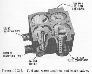
The fuel and water check valves and strainers are mounted in a single housing, as shown in figure 12C13. The strainers remove any foreign matter from the fuel and water. Before firing, spring pressure keeps the valves closed, keeping fuel and water out of the combustion flask. On firing, pressure in the fuel and water compartments unseats the valves.
12C7. Restriction valves
Before entering the combustion flask, both fuel and water flow through restriction valves, which control the speed of flow. Working-pressure air, before it enters the combustion flask, also flows through a restriction valve. The restriction causes a small decrease in air pressure; as a result, the pressure in the fuel and water compartments is higher than that in the combustion flask. It is this differential pressure—from 40 to 75 psi—that forces fuel and water into the flask.
12C8. Starting valve
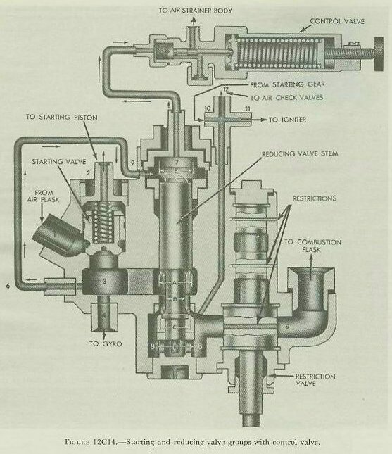
The starting valve, reducing valve, and restriction valve are located in a single housing, as shown in figure 12C14. When the stop valve is opened, flask-pressure air flows in and surrounds the bottom part of the starting valve. While the stop valve is being opened, air fills the space above the starting valve through a small passage. When the torpedo is fired, the starting gear vents the air line and the pressure above the starting valve drops. The pressure at the bottom of the valve forces it open, and flask-pressure air flows to the gyro-spinning mechanism and reducing valve.
12C9. Reducing and control valves
The reducing valve (figure 12C14) works by balancing air pressure forces acting on different cross-sectional areas of the valve stem. Flask-pressure air goes through the control pipe into the control chamber, where it pushes down on the valve stem area E, forcing the valve open. As the valve opens, air flows into the reduced-pressure chamber, pushing up on area D to tend to close the valve. The valve stem moves until the upward and downward forces exactly balance.
The control valve is a spring-regulated leak-off for the control chamber that keeps the pressure in the control chamber constant. As the torpedo uses up the air in the air flask and the flask pressure gradually drops, the working pressure remains constant—if the pressure in the reduced-pressure chamber starts to drop, the valve opens wider to compensate.
From the reduced-pressure chamber, working-pressure air goes to the igniter, to the two air check valves, and through the restriction in the restriction valve to the combustion flask. The two upper passages in the restriction valve stem control fuel and water delivery; turning the restriction valve stem changes the delivery rate and thus the running speed of the torpedo.
12C10. Starting gear
When the torpedo is fired, the starting gear vents the pressure above the piston of the starting valve, allowing the starting valve to open. Figure 12C15 represents the starting gear of a Mark 15 torpedo.
The starting gear is operated by two separate devices—the starting lever and the inertia weight. When the torpedo begins to move forward in the tube, a tripping latch strikes the starting lever and throws it aft. The starting lever moves the piston lifter upward toward the starting piston, but does not lift the piston. As the torpedo gains momentum, the inertia weight completes the upward movement of the piston lifter and opens the valve. A spring-loaded latch holds the starting gear open throughout the run.
Neither the starting lever nor the inertia weight can operate the starting gear alone. Both must act together before the valve can open—a safety feature that prevents accidentally starting the torpedo before it is fired.

D. Superheating System of a Mark 15 Torpedo
12D1. General
Figure 12D1 is a diagram of the superheating system of a Mark 15 torpedo. The system consists of the combustion flask, the devices through which air, fuel, and water enter the flask, the igniter, the nozzles through which combustion gases flow to the turbine blades, and the nozzle valve. All of these parts are mounted on the forward face of the turbine bulkhead.
12D2. Functional description
Both speed and range are increased considerably by superheating the compressed air. This is done in the combustion flask, where fuel is burned in a stream of working-pressure air. In burning, the liquid fuel is converted to gases, which add their volume to that of the compressed air. The heat of combustion increases the pressure, and therefore the speed at which the combustion gases strike the turbine blades. The water sprayed into the flask to cool it turns to steam and adds to the volume of gases. The water contributes no energy to the system, but it does take energy that would otherwise be wasted as heat, and makes it do useful work.
The fuel spray delivers fuel in the form of a fine mist. The fuel and the whirling air mix thoroughly, and the igniter starts them burning. Once ignited, the fuel and air mixture continues to burn without any further help from the igniter. The igniter burns out after about 6 seconds.
The hot combustion gases pass at high velocity from the combustion flask to the nozzle unit. They strike the blades of the first turbine wheel, and start it spinning. The gases are deflected from the blades of the first turbine wheel and strike those of the second, spinning it in the opposite direction.
The nozzle valve (figure 12D1) is a part of the speed-change mechanism. When the nozzle valve is raised a short distance it closes 3 of the 5 nozzles, leaving only 2 open. When raised all the way, the valve closes all of the nozzles but one.

12D3. Igniter
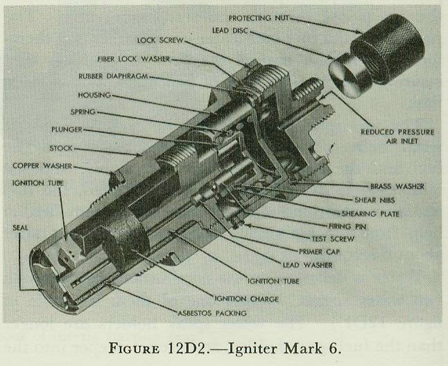
The igniter is screwed into a threaded opening in the combustion flask. During transportation or overhaul, a dummy igniter keeps out dirt and moisture. During preparations for firing, the dummy is removed and replaced by the real igniter. Figure 12D2 shows a cutaway view of the igniter. When the torpedo is launched, air from the reducing valve enters through the reduced-pressure air inlet. Air pressure, acting through the rubber diaphragm, presses down on the housing. The sheer nibs hold the housing in place until pressure builds up to about 250 psi, then suddenly give way. The housing and the firing pins snap down, firing the primer caps. Flame from the caps lights the ignition charge, which burns from the bottom upward.
12D4. Speed-change mechanism
The speed-change mechanism allows the torpedo tube crew to change the torpedo’s running speed by turning a single shaft accessible from outside the torpedo. Figure 12D3 is a diagrammatic view of the speed-change mechanism of a Mark 15 torpedo. Turning the operating shaft does three things: (1) it changes the size of the restrictions in the restriction valve; (2) it changes the number of nozzles covered by the nozzle valve; and (3) it changes the gear ratio of the main engine. Speed-setting data for the Mark 15 torpedo is summarized in the table below.


E. Main Engine of a Mark 15 Torpedo
12E1. General
The main engine is located entirely within the afterbody, and is supported by A-frames secured to the after side of the turbine bulkhead. It consists of the turbine wheels, gear reduction train, and propeller shafts, along with the frames, spindles, shafts, and bearings that support these parts, and the oiling system that lubricates them. Figure 12E1 shows the main engine of a Mark 15 torpedo viewed from the starboard side.

12E2. Functional description
The main engine converts turbine-wheel rotation into propeller rotation. Because of the high velocity at which combustion gases strike the turbines, the turbine wheels must turn at high speed. But the propellers must turn more slowly and develop higher torque, requiring a gear reduction train. The torpedo is provided with two propellers rotating in opposite directions at the same speed—this prevents the torque of a single propeller from rolling the torpedo. The main engine combines the two unequal torques developed by the two turbine wheels, then divides this force equally between the two counter-rotating propellers.
12E3. Gear train
Figure 12E2 is a schematic diagram of the main engine. Each of the two turbine wheels is mounted on a separate spindle. The first turbine spindle is short and hollow, carrying the first turbine pinion at its lower end. The second turbine spindle passes through the opening in the first spindle.

The hot combustion gases reach about 4,000 feet per second as they pass through the nozzles, spinning the first (lower) turbine wheel counterclockwise (as viewed from the top). The gases are deflected from the first turbine and strike the second (upper) turbine, spinning it clockwise. Each of the two bevel pinions meshes with both bevel gears. Working together, they turn the two bevel gears. The forward bevel gear turns the after (inner) propeller shaft; the after bevel gear turns the forward (outer) propeller shaft. Because the two propeller shafts are linked through the bevel gears and bevel pinions, they turn in opposite directions at the same speed.
12E4. Turbines and turbine spindles
Figure 12E3 shows the turbine and spindle assembly. In both turbines, the blades are of crescent-shaped cross section. The turbine band is made up of overlapping segments; the clearance at the butt ends gives them room to expand when hot. The blades of the second turbine curve in the opposite direction from those of the first, and are slightly larger so that the gases can keep expanding as they pass through.

12E5. Crosshead assembly
Figure 12E4 shows the crosshead. Its outer ends are supported in the two A-frames. Bronze bushings on the two crosshead shafts serve as bearings for the main drive gears and bevel pinions. Note the spiral oil grooves on the surface of the bushings. The after propeller shaft passes through the crosshead in a floating bronze bushing. The forward bevel gear is keyed to the after (inner) propeller shaft; the after bevel gear is keyed to the forward (outer) propeller shaft.

12E6. Engine thrust
As the propellers turn, they develop a thrust transmitted to their shafts. The crosshead transmits the forward thrust through the A-frames and the turbine bulkhead to the shell of the torpedo. The after propeller shaft applies its thrust to a thrust bearing mounted on the after side of the turbine spindle casing.
12E7. Engine balancing
The engine parts of a Mark 15 torpedo rotate fast enough to develop considerable gyroscopic action. To keep this from interfering with the steering mechanism, the main engine is balanced—the gyroscopic force of each principal rotating part is balanced by a similar part rotating in the opposite direction. Counter-rotating pairs include the turbine wheels, turbine pinions, main drive gears, bevel pinions, and bevel gears.
12E8. Side gear assembly
The speed-change mechanism of the Mark 15 torpedo includes a means for changing the gear ratio in the main engine by interposing idler gears called side gears between the turbine pinions and the main drive gears. Figure 12E5 is a diagram representing the side gears in the low-speed and high-speed settings. When the speed-setting socket is turned, the cam rotates, moving the operating rod, which turns the side gear carrier so that either the high-power or low-power side gear may be engaged with the main drive gear.

12E9. Oiling system
The after propeller shaft bearings are lubricated by grease. All other bearings and gear teeth are supplied with oil throughout the torpedo run. Figure 12E6 is a diagram of the oiling system. Oil flows from two oil tanks to the reservoir, ensuring a steady supply to the pump. The pump, driven by a worm on the bottom of the second turbine spindle, forces oil through two separate outlets—one for the turbine spindle bearings and one for the crosshead. Turning gears whip leaking oil into a fog that lubricates parts not supplied directly by the oil pump.

12E10. Exhaust system
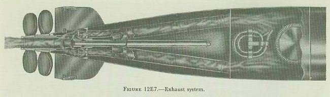
Figure 12E7 shows the exhaust system of a Mark 15 torpedo, looking down from the top. Two tubes carry exhaust gases from the space above the turbines to the tail section, where each tube separates into two branches. The exhaust gases enter the tail section through four openings in the after bulkhead of the afterbody. Oil fog is kept out of the exhaust system by a turbine oil guard pan and an oil deflector ring above the upper turbine spindle bearing, preventing the torpedo from leaving a heavy wake of smoke.
F. Control Systems of a Mark 15 Torpedo
12F1. General
The torpedo is provided with two pairs of rudders—one horizontal and one vertical. The vertical rudders control the steering of the torpedo to left or right, and keep it on its preset course. The horizontal rudders steer the torpedo up or down, to keep it at its preset depth.
The two control systems—one for steering and one for depth—are located in the afterbody. The steering system consists of a gyro, a pallet mechanism, and a steering engine. The depth system consists of a diaphragm, pendulum, and depth engine. Each engine operates a rod extending aft through a packing in the after bulkhead of the afterbody, connected to its pair of rudders through a semicircular yoke.
12F2. Functional description
The control mechanisms have been called the “brains” of the torpedo. Each of the two control mechanisms consists of three parts: a sensing part, a detecting part, and an engine.
Sensing parts. In the steering mechanism, the sensing part is the gyroscope. Throughout the torpedo run, the axis of the gyro always points in the same direction. The depth mechanism has two sensing parts—a diaphragm (which measures depth by responding to water pressure) and a pendulum (which detects the running attitude of the torpedo).
Detecting parts. In the steering mechanism, the detecting part is the pallet mechanism. If the torpedo turns left or right from its course, the pallet mechanism detects the difference and sends correcting orders to the steering engine. In the depth mechanism, the diaphragm and pendulum are linked together and work together to send corrective signals to the depth engine.
Engines. The steering engine throws the vertical steering rudders in the direction required to bring the torpedo back on course. The depth engine moves the horizontal depth rudders to bring the torpedo back to its preset depth. Both engines are powered by working-pressure air.

12F3. Control mechanism assembly
Figure 12F1 shows the control mechanism assembly mounted on an oval base plate that fits a flanged opening in the lower side of the afterbody shell. The vertical cylinder in the center is the gyro pot. The pallet mechanism, which detects the relative position of the gyro axis, is mounted on the top plate at the top of the gyro pot. For an angle shot, the top plate and pallet mechanism are rotated through a shaft and gear train by a setting socket on the outside of the afterbody shell.
12F4. Gyro
Throughout the torpedo run, the axis of the spinning gyro remains rigid in space—it points constantly in the same direction. If the torpedo turns off its proper course, it turns with respect to the gyro axis, which remains fixed. The pallet mechanism detects this relative turning and sends corrective orders to the steering engine.
Figure 12F2 shows how a torpedo gyro is assembled in its gimbals. Most of the gyro wheel’s weight is concentrated in its outer rim to increase gyroscopic action. Low-pressure air from the gyro reducer strikes the spinning buckets on the outer rim to maintain spin throughout the run. The gyro spins on a fore-and-aft horizontal axis within the inner gimbal. The inner gimbal rotates on a horizontal axis at right angles to the gyro wheel axis. The outer gimbal rotates on a vertical axis in the gyro pot. Thus the gyro wheel has three degrees of freedom and is free to turn in any direction with respect to the torpedo.

12F5. Spinning and unlocking mechanism
At the instant of firing, the gyro is rigidly locked with its axis of spin parallel to the axis of the torpedo by the centering pin of the spinning and unlocking mechanism. When the starting valve opens, flask-pressure air enters the spinning mechanism and spins its turbine, bringing the gyro wheel to full speed in just over half a second. The spinning gear then snaps out of engagement with the gyro, and the centering pin snaps out of its cavity, unlocking the gyro and leaving it free to control the steering of the torpedo.
12F6. Pallet mechanism
Figure 12F3 shows the pallet mechanism mounted on the gyro top plate. The pallet driving gear is turned by a spur gear on the forward (outer) propeller shaft.

Figure 12F4 is a diagram of the whole steering mechanism. An eccentric cam on the eccentric gear shaft gives a fore-and-aft motion to the pallet shaft holder and the pallet shaft. The pallet shaft and its pallet (at the top) and two cam pawls (at the bottom) have a continual fore-and-aft motion throughout the torpedo run.
The cam on the cam plate indicates the desired course of the torpedo. If the torpedo is exactly on course during the forward stroke of the pallet shaft, the two cam pawls straddle the cam and the pallet shaft is not rotated. If the torpedo is off course, one cam pawl strikes the cam, rotating the pallet shaft. On the next backward stroke, the pallet strikes one of the pallet pawls, moving the steering engine valve. The steering engine then throws the rudders in the direction necessary to bring the torpedo back on course.


The actual track of the torpedo is not a straight line. The rudder oscillates constantly, and the torpedo weaves back and forth across its course. But because the pallet mechanism is sensitive, the weaving is small; the actual track is very close to a straight line.
12F7. Angle fire
It is often inconvenient or impossible to launch a torpedo in the direction required by the fire control problem—especially with fixed tubes. In such situations angle fire is used. The gyro angle is set through one of the gyro setting sockets on the outside of the torpedo. The socket, through a gear train, turns the gyro top plate through the desired gyro angle, carrying the whole pallet mechanism with it. Figure 12F6 shows the angle of the gyro, pallet, and rudder for both a straight shot (A–B) and an angle shot (C–D).

12F8. Depth mechanism
While the steering mechanism brings the torpedo onto its proper course, the depth mechanism brings it to its proper depth. This system has two sensing parts—a hydrostatic diaphragm and a pendulum. The flexible diaphragm is open to sea water on one side; a spring resists the pressure of the water. The stronger the water pressure, the farther the diaphragm moves. The pendulum tends to hang straight down, and can determine whether the torpedo is tilted up or down.
Figure 12F7 shows schematically how the diaphragm and pendulum work together. Assume the torpedo is below its set depth with its axis horizontal. Water pressure pushes the diaphragm down, rocking the diaphragm lever counterclockwise, which swings the pendulum forward and pulls the depth engine valve rod forward. The depth engine applies up rudder and the torpedo begins to climb. As the torpedo turns upward, gravity tends to pull the pendulum aft against the action of the diaphragm, reducing the up rudder. When the climbing angle is just steep enough to balance the diaphragm action, the rudder is in neutral—but the torpedo is still climbing. As it climbs, water pressure decreases, letting the pendulum apply down rudder. The torpedo levels off and reaches its set depth at a slow rate of climb. In this way the pendulum tends to prevent overshooting.

Figure 12F8 is a cutaway view of the depth mechanism, showing the actual appearance and location of the parts shown schematically in figure 12F7. Like the steering engine, the depth engine works on compressed air from the reducing valve. But while the steering engine piston goes full-throw in one direction or the other, the piston of the depth engine follows the valve exactly and can hold the horizontal depth rudders at any position between full up and full down.

G. Tail Section of a Mark 15 Torpedo
12G1. General
The tail section is a short, truncated cone. Its principal parts are: (1) the two propellers; (2) the tail blades and rudders; (3) the sleeves and hubs that support the propellers; and (4) the rods and yokes that operate the rudders.

12G2. Construction
Figure 12G1 is a cutaway view of the tail section. The forward propeller sleeve is keyed to the forward propeller shaft and secured by screws. The after propeller sleeve is secured to the after propeller shaft in the same way. The forward propeller sleeve turns in the tail bearing. The after propeller sleeve turns in four bronze bushings inside the forward sleeve. The grease reservoir shell holds a supply of grease inside the after propeller sleeve; when the torpedo is under way, the hot exhaust gases melt the grease, and centrifugal force pushes it through small passages to lubricate the bushings and tail bearing.
The exhaust gases pass through openings in the after bulkhead of the afterbody and enter the tail through exhaust valves. Springs in the exhaust valves hold them shut until the pressure of exhaust gases forces them open—thus keeping water out of the afterbody at the end of an exercise run and when the torpedo is in a flooded submarine tube. The exhaust gases flow into the tail, into the propeller sleeves through holes in their forward ends, and out to the sea. Each of the two propellers has four blades.
The four tail blades are riveted to projections on the outside of the tail cone. They stabilize the torpedo as it travels through the water. The two pairs of rudders are mounted at the after edges of the tail blades. The outer bearings of the rudders have a double purpose: their outer edges serve as bearing surfaces to guide the tail as the torpedo slides through the torpedo tube.
H. Aircraft Torpedoes
12H1. Construction and use
Aircraft torpedoes came into common tactical use during World War II as alternate weapons to aircraft bombs for use in attacks on surface ships. Aircraft torpedoes must be able to withstand heavy water impacts. They must also be capable of maintaining stable flight from plane to water, and a stable course through the water to the target. The Mark 13 torpedo, shown in figure 12H1, is one of the older types still in service use. It is similar to the Mark 15 torpedo but differs in certain details of size and design, including the incorporation of special stabilization elements necessary for effective launching from aircraft.
An aircraft torpedo is usually suspended between two racks. A small stop bolt projecting downward from the plane into a hole in the torpedo casing prevents fore-and-aft slipping. When one end of each cable is released, the torpedo falls away.

12H2. Mark 13 torpedo
The Mark 13 torpedo differs from the Mark 15 torpedo in the following ways:
1. The Mark 13 torpedo has better provision for air stabilization, being much shorter and slightly larger in diameter: 13 feet 5 inches long, 22.42 inches in diameter.
2. The Mark 13 torpedo has greater capacity for withstanding water impact.
3. The Mark 13 torpedo contains a smaller explosive charge: 600 pounds of HBX.
4. The Mark 13 torpedo has a shorter designed range: 5,700 yards.
5. The Mark 13 torpedo has a single speed: 33.5 knots.
6. The Mark 13 torpedo has a water trip delay valve to prevent ignition until the torpedo enters the water.
7. The Mark 13 torpedo has a shroud ring around its tail vanes, which minimizes hooking and broaching upon water entry, and makes for greater stability during the water run.
8. The Mark 13 torpedo is rigged for launching with a box-shaped plywood stabilizer fitted over the fins and shroud ring. This stabilizer causes the torpedo to fall in a smooth curve and enter the water head first. A parachute drogue stabilizer has been designed as a substitute for the box stabilizer.
9. The Mark 13 torpedo has a drag ring fitted over its head to slow the torpedo’s rate of fall, reduce wobbling, and act as a shock absorber on water impact. The stabilizer and drag ring are shown in figure 12H2.
Near the after end of the torpedo is a starting lever. When the torpedo is installed on the plane, a toggle is hooked to this lever and attached to the aircraft by a lanyard. When the torpedo is released, action of the lanyard and toggle trips the starting lever, but a water trip delay valve prevents the combustion flask from firing until water entry. A gyro-locking mechanism is also provided; the gyro begins to spin on release from the plane, keeping the torpedo on the course determined by the direction of aircraft travel at the instant of release.

12H3. The aircraft-torpedo problem
The basic problem in launching a torpedo from an aircraft is to put the torpedo in the water on a collision course with the target. The pilot must be able to: (1) estimate target angle (see figure 12H3); (2) estimate target speed; (3) estimate and utilize proper lead; and (4) release the torpedo at the sighting angle which will produce a collision course.
Speed of the plane at the point of release is established by doctrine to ensure that the torpedo will enter the water at an angle between 20 and 33 degrees, and not deep-dive or ricochet. When the plane has a speed in excess of 150 knots and the water is at least 150 feet deep, an entrance angle of 26 to 30 degrees is preferable. The torpedo will assume its preset running depth (up to 50 feet) after water travel of 300 yards; the exploder mechanism is armed after a water run of 200 yards.

I. Other Types of Torpedoes
12I1. General
All United States Navy gas-steam torpedoes are similar in principle to the Marks 15 and 13 described above. Electric torpedoes differ from the gas-steam type in respect to their main power plants. In all the non-homing torpedoes, the steering and depth mechanisms are similar, if not exactly the same. And war heads and exercise heads, although they differ in size, are basically similar.
12I2. Torpedoes Mark 14 type and Mark 23 type
These torpedoes are only 20½ feet long, to fit in submarine tubes. The Mark 14 has two speeds: the low-power setting gives a range of 9,000 yards at approximately 32 knots, and the high-power setting gives a range of 4,500 yards at 46 knots. Its war head contains about 700 pounds of high explosive.
There are no side-gear assemblies in the main engine of this torpedo. The two speed settings are obtained by changing the number of nozzle jets in use (two for low speed, five for high) and by altering the size of the restrictions in the air, fuel, and water delivery lines. The Mark 14 torpedo has a governor that stops the torpedo if the starting lever is tripped accidentally, preventing excessive speed and safeguarding personnel.
The Mark 23 torpedo is a Mark 14 torpedo from which the speed-change mechanism has been removed, leaving all five nozzles open. The restriction valve is locked in high power, and the engine can be operated at high speed only.
12I3. Torpedo Mark 18 type
The Mark 18 is an electrically propelled torpedo designed for use in submarines. It is single-speed, designed to run for 4,000 yards at an average speed of about 29 knots. The primary advantage of the Mark 18 is that it is wakeless.
In place of an air-flask section this torpedo has a battery compartment, which contains a lead-acid storage battery, a hydrogen eliminator, and a ventilating system. The battery runs a 90-horsepower series electric motor whose armature is connected by the main drive shaft and gearing to two counter-rotating propellers. Compressed air required to close the starting switch, spin the gyro, and operate the depth and steering engines is stored at 3,000 psi in three small flasks in the afterbody. The war head contains about 600 pounds of high explosive.
12I4. Torpedo Mark 16 type
The Mark 16 is a single-speed 21-inch by 21½-foot submarine torpedo. It is a gas-steam torpedo in which hydrogen peroxide (NAVOL), instead of compressed air, supplies the oxygen required for combustion of the fuel. This allows the Mark 16 to carry as much explosive as the Mark 15 and to have greater high-speed range, while not exceeding the Mark 14 in size.
The source of oxygen and part of the water for the combustion cycle is the NAVOL—a solution of hydrogen peroxide (H2O2) in water. Hydrogen peroxide, passing through a chamber containing a catalyst, decomposes with evolution of heat to form water (steam) and oxygen. The oxygen unites with the fuel (alcohol) in the combustion pot, combustion being initiated by an igniter of conventional type. The resulting hot gases mix with steam and drive the main-engine turbines.
By using NAVOL, the torpedoes require no air fed to the combustion pot; consequently no nitrogen is present in the exhaust to rise to the surface and leave the customary wake. There is, however, a small amount of nonsoluble gas from alcohol combustion, leaving a very small wake that is practically invisible except in flat, calm water. The main engine is a turbine with reduction gearing similar in principle to the Mark 15, but with a horizontal turbine axis and spur gears rather than bevel gears for speed reduction.
12I5. Electrically set torpedoes
In the torpedoes described above, the gyro angle and running depth are ordinarily set mechanically by inserting a spindle into the setting socket and turning it. In several modifications of the torpedoes mentioned above, and in practically all homing torpedoes, the settings are made electrically. A multi-conductor cable enters the breech of the torpedo tube and is connected by a plug and socket to a similar cable in the afterbody of the torpedo. When the proper electrical inputs are supplied, servomechanisms in the torpedo automatically set the proper depth and gyro angle. At the instant of firing, the cable is automatically cut off close to the torpedo.
The electric setting system has several advantages: settings are relatively exact, it eliminates several sources of error inherent in the mechanical setting system, settings can be made right up to the instant of launching, and the system can easily be integrated with advanced fire control systems so that setting signals are supplied automatically.
12I6. Homing torpedoes
Homing torpedoes can also follow a gyro course; in addition, they can search for a target and, when they find one, chase it until they score a hit. Some types can switch back and forth between gyro control, search pattern, and homing control as appropriate.
At present, homing torpedoes are acoustic (operated by sound). Active types send out short pulses of sound and listen for echoes from the target; when an echo is detected, the torpedo steers itself toward the source. Passive types merely listen for target sounds (such as propeller and machinery noises) and then steer toward the source.
The homing torpedo has the same safety devices as the air-steam type. Its exploder is armed both mechanically and electrically, and remains safe until the torpedo has traveled a safe distance from the firing ship. Homing torpedoes, almost without exception, are powered by electric motors and batteries. Several types are somewhat smaller than air-steam torpedoes, and several have a single propeller rather than two.
J. Above-Water Torpedo Tubes
12J1. Function
Torpedo tubes serve the following purposes:
1. House and protect the torpedo (including heating in cold weather) until the instant of firing.
2. Provide means for setting torpedo gyro angle, running depth, and, where required, torpedo speed, up to the instant of firing.
3. Expel the torpedo with sufficient force to clear the firing ship and with such velocity and direction that it will remain on its firing course until its engine develops enough power for self-propulsion.
4. As expulsion starts, trigger the torpedo so as to start its engine and gyro.
12J2. Type and location
Above-water tubes may be classed as trainable or fixed. Until after World War II, United States Navy destroyers armed with torpedoes all carried trainable tubes. Destroyers mount either the Mark 14 or the Mark 15 quintuple tubes. Trainable tubes require large clear deck areas and are mounted topside on the ship’s centerline as shown in figure 1B2. From this location torpedoes can be fired through limited arcs of train on either side of the ship.
In the latter phases of World War II the necessity for increasing antiaircraft armament put a high premium on topside deck space. New destroyer and escort designs therefore featured above-water torpedo tubes in locations other than the weather deck—such tubes are housed and fixed (non-trainable). With fixed tubes, greater gyro angles must be used in firing than from trainable tubes, and since torpedoes tend to depart more widely from their predicted courses when fired with large gyro angles, this is a disadvantage. Also, tubes must be carried on both sides of the ship. Fixed tube designs include the Marks 23 and 24.
12J3. 21-inch Above-Water Torpedo Tube Mark 14
Each Mark 14 torpedo tube consists of five barrels, supported in a single saddle which functions like the carriage of a gun. The saddle rests on a roller bearing assembly supported by a stand containing a training circle. The tube is normally trained by an electric-hydraulic drive similar to a gun mount train drive. See figure 12J1.

Each barrel is an assembly of a main barrel, a spoon, and a spoon extension. Within the barrel at the bottom are rollers to facilitate loading. A T-shaped guide slot runs the length of the top of the barrel; the guide stud on the torpedo rides in this slot as the torpedo is fired, preventing the torpedo from dropping downward before the tail has cleared the main barrel.
Torpedoes are expelled from each barrel individually by an impulse charge of black powder fired in the firing mechanism on top of the barrel. A torpedo stop keeps the torpedo from sliding in the barrel; a tripping latch projects into the barrel and engages the starting lever of the torpedo as it begins to move forward.
Atop the barrels are a seat for the trainer and gyro setter, the train controls, and the sight and fire control apparatus. Also on top, within easy reach of the crew, are the gyro-setting, depth-setting, and speed-setting mechanisms.
12J4. Torpedo-setting mechanism
The depth-setting mechanisms are arranged to set the five torpedoes simultaneously with the same depth setting. A depth-setting hand crank operates through gears and shafts to turn depth-setting sockets in each barrel, turning a dial index that shows the depth set. Sockets must be disengaged before firing.
The speed-setting mechanisms of the barrels are separate. Each consists of a permanently mounted wrench with a spring that holds the spindle up out of engagement with the torpedo’s speed-setting socket except when pushed down by hand; a cam allows the wrench to spring up only when properly positioned at the HIGH, INTERMEDIATE, or LOW speed setting. The wrench and spindle must never be left in the down position.
The gyro-setting mechanism provides a means for: (1) setting the gyros of all five torpedoes to any desired basic gyro angle; (2) setting any desired spread up to 10 degrees; and (3) engaging and withdrawing the gyro-setting spindles at will. Two separate handcranks are used, one for the basic gyro angle and one for the spread-angle setting. They work together through a differential at each tube to set the proper resultant angle on each torpedo. Spindles must be disengaged before the torpedoes are fired.
12J5. Torpedo tube sight and torpedo course indicator
The trainer and the gyro setter are guided in determining the proper firing course for the torpedoes either by the torpedo tube sight (in local control) or by the dials of the torpedo course indicator (in remote control). Since an understanding of either of these instruments presupposes a comprehension of the torpedo fire control problem, they are discussed in Volume II.
12J6. 21-inch Above-Water Torpedo Tubes Marks 23 and 24
Figure 12J2 represents a single-barrel fixed-type nontrainable torpedo tube designed to mount singly or in groups of two or more on each side of a vessel. The tubes are mounted athwartship within the superstructure, with muzzles extending through the sides of the deck house. The tubes are constructed of lightweight aluminum alloy. They are air-fired and are suitable for launching only torpedoes having electrically set torpedo controls. The breech and muzzle doors are so interlocked that firing can occur only when the breech door is closed and locked and the muzzle door is opened.
Torpedo Tube Mark 23 is designed to launch 21-inch torpedoes with a length not exceeding 161 inches. Torpedo Tube Mark 24 is designed to launch 21-inch torpedoes with a length not exceeding 246 inches. Both tubes are supplied with adapter rings that permit launching a 19-inch diameter torpedo.
